Figure 14, Crosspiece with critical orifice and o-ring seals – M&C TechGroup DIL-1_(H) Operator's manual User Manual
Page 27
27
Gas sampling and gas conditioning technology
2-1.1.7.6-ME
16.2
CLEANING OF THE CRITICAL ORIFICE AND CHECK OR CHANGE OF THE O-
RINGS
W A R N I N G !
Do not clean the critical orifice mechanically.
Cleaning should be effected in an ultrasonic bath !
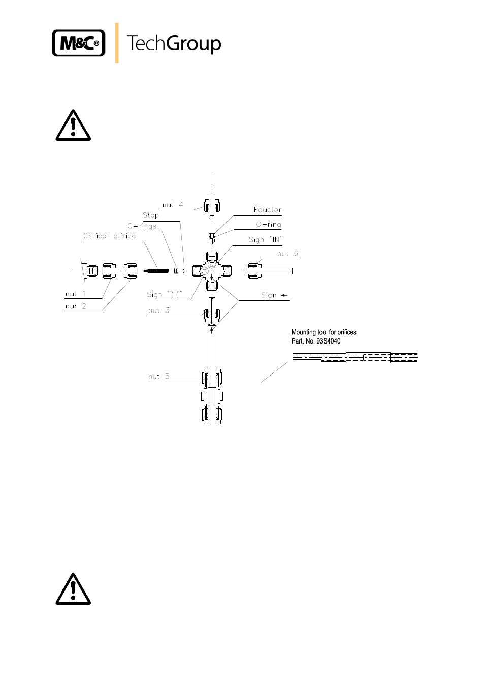
Figure 13 shows the position of the orifice in the crosspiece and the O-ring seals.
Figure 14
Crosspiece with critical orifice and O-ring seals
Please proceed as follows:
Loosen union nut 3 and remove the jet pipe;
Loosen nut 2 and remove the pipe piece with both nuts;
Push the injection nozzle out of the jet pipe side by using the mounting tools (item 8, figure 14);
Push the critical orifice with its nozzle seat and o-ring carefully from the back side of the cross-
piece by using the mounting tool (item 8, figure 14);
Check the o-rings and change them if necessary;
Push the new orifice or the cleaned old one into the o-rings until block.
Now, the dilution unit can be reassembled in reverse order.
W A R N I N G !
The Swagelok
®
fittings must be carefully tightened to avoid damage
of the internal components. Do not tighten the fittings too fast.
If a fitting is believed to be leaking, do not tighten further. Disas-
semble the fitting completely and tighten it again.
8