Dilution principle, Figure 7 – M&C TechGroup DIL-1_(H) Operator's manual User Manual
Page 14
14
Gas sampling and gas conditioning technology
2-1.1.7.6-ME
9
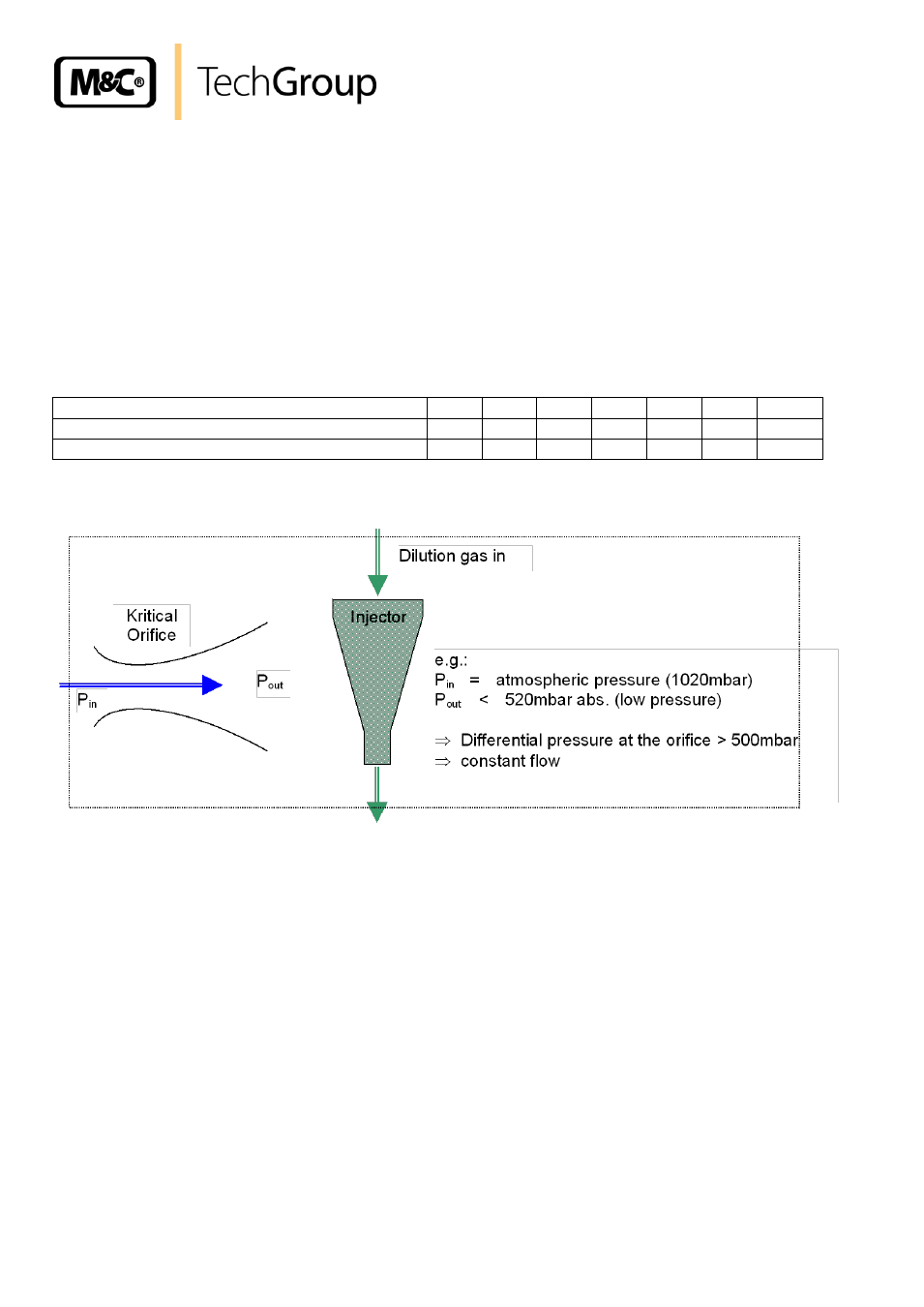
DILUTION PRINCIPLE
The functional principle of the dilution unit is based on ultrasonic flow through a critical orifice (see Fig.
4). The flow through the orifice is constant when the differential pressure via the orifice is higher than
500 mbar. For the atmospheric inlet pressure (Pin = 1020 mbar), this means a pressure at the orifice
outlet (Pout) of less than 520 mbar absolute.
The necessary vacuum at the orifice outlet is produced by an injector operated with dilution gas.
Depending on the critical orifice selected, dilution rates can be between 10:1 and 500:1. The table be-
low gives an overview of the dilution factor and sample gas volume using the injector I (480
– 600
Nl/h):
Orifice type
a
b
c
d
e
f
g
Dilution ratio*
500:1 200:1 100:1 50:1
30:1
20:1
10:1
Volume flow through the orifice [Nl/h]
1,4
2,7
5,5
11
19
28
55
* with Injector II 50:1 to 2000:1
Figure 7
Dilution principle
How to check the dilution ratios and the exact adjustment of the pressure conditions are described in
chapter 14.1.