Disassembly of the crosspiece, Figure 13, Explosion drawing of the dilution crosspiece – M&C TechGroup DIL-1_(H) Operator's manual User Manual
Page 26
26
Gas sampling and gas conditioning technology
2-1.1.7.6-ME
16.1
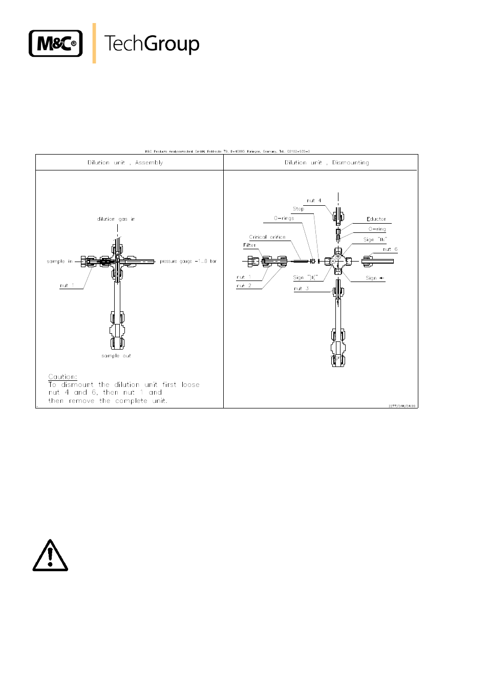
DISASSEMBLY OF THE CROSSPIECE
For disassembling of the crosspiece, the heating of the heated dilution unit should be switched off so
that the unit can cool down.
Figure 13 shows the explosion drawing of the dilution crosspiece.
Figure 13
Explosion drawing of the dilution crosspiece
We recommend to proceed according to the following steps:
Remove the insulation cover of the dilution unit, if applicable;
Remove all tube connectors on the dilution crosspiece. These are:
- Depression manometer nut 6
- Dilution gas inlet nut 4
- Sample gas outlet nut 5
- Removal of nut 1.
W A R N I N G !
Nut 2 must only be removed after having disassembled the dilution
cross. Disregard may lead to destruction of the critical orifice!
Now, the dilution crosspiece is accessible for further maintenance and repair work.
- SP10 Operator's manual (14 pages)
- N9 KP18 Operator's manual (21 pages)
- SP2000_20SS 150 Data sheet (3 pages)
- SP3100 Data sheet (6 pages)
- PSP4000-H _C _T Data sheet (4 pages)
- SP2200-H_C_I_BB_F Data sheet (2 pages)
- SP35-H... for gas sample probe SP2000-H... Data sheet (2 pages)
- FP-BF Data sheet (2 pages)
- SP3200 Operator's manual (28 pages)
- FPF-0,1 Operator's manual (2 pages)
- PSS-10_1 Operator's manual (23 pages)
- CSS-V2 Data sheet (3 pages)
- PMA 50 EEX Operator's manual (48 pages)
- MP30 Operator's manual (18 pages)
- SP2600-H_C_I_BB_F_0,1GF190 Data sheet (3 pages)
- SR25.1_Ex Operator's manual (22 pages)
- PMA 10S Operator's manual (27 pages)
- CSS-M_W Data sheet (3 pages)
- PAS-500 Operator's manual (20 pages)
- SP2000H320_DIL... Data sheet (3 pages)
- SP3200 Data sheet (6 pages)
- FA-1_2_3,bi Operator's manual (24 pages)
- SR25 Data sheet (2 pages)
- SP3000 Data sheet (4 pages)
- PAS Series Data sheet (2 pages)
- CG Series Data sheet (2 pages)
- ECP 20-2 Data sheet (3 pages)
- MP30-EX Data sheet (2 pages)
- PSP4000-H_C_T Operator's manual (24 pages)
- DIL-U Data sheet (2 pages)
- ADS-So Data sheet (2 pages)
- VC-2-SL Operator's manual (18 pages)
- ECM-ExII Operator's manual (39 pages)
- MP12 Operator's manual (17 pages)
- FPF+ Data sheet (2 pages)
- KS 2.Ex Operator's manual (17 pages)
- PMA 50 EEX Data sheet (3 pages)
- PMA 10S Data sheet (3 pages)
- Gas Sample Probes Series SP Data sheet (2 pages)
- BA-C Operator's manual (16 pages)
- MV3_2-H Series Operator's manual (18 pages)
- VC-2-SL Data sheet (3 pages)
- FM-200K-H_FA Operator's manual (16 pages)
- SP 30-H.._EX2 Operator's manual (16 pages)
- SP2006-H280_DIL Operator's manual (35 pages)