M&C TechGroup PMA 100 Operator's manual User Manual
Page 10
M&C Products Analysentechnik GmbH
9-3.12-ME
- 10 -
8.2.1
mA output
The mA output is available on the back panel of the
PMA100 (see fig.8) at the 15-pole Sub-D socket X3. The
following figure shows the configuration of the terminal.
For multichannel version the outputs are arranged as
follows:
1
channel 1,
2
channel 2,
3
channel 3,
4
channel 4.
The menu-driven handling of the mA outputs is described in
chapter 12.
8.2.2
In- and output contacts
Fig. 9 shows the configuration of the terminal X4. The
following connections are available at the 25-pole Sub-D
plug:
• four binary inputs, In1 to In4, with 12V - 24V, max. 20mA,
• four binary output contacts, Out1 to Out4, with 48V,
max. 500mA,
• one alarm contact, Alarm MC and Alarm NO, with 48V,
max. 500mA,
• one status contact output, Status MC and Status NO,
with 48V, max. 500mA. and
• one supply power contact, Out +24V and Out 0V, with
24V, max. 100mA.
The menu-driven handling of the in- and outputs is
described in chapter 12.
8.2.3
Connector for solenoid valves
Fig. 10 shows the 25-pole Sub-D socket X5 with the supply
power to control three external solenoid valves. At the moment
three conections are available:
• pin 2 connection for the zero gas solenoid valve, 24V,
max. 400mA,
• pin 3 connection for the span gas solenoid valve, 24V,
max. 400mA, and
• pin 5 connection for the sample gas solenoid valve, 24V,
max. 400mA.
The menu-driven handling of the in- and outputs is
described in chapter 12.
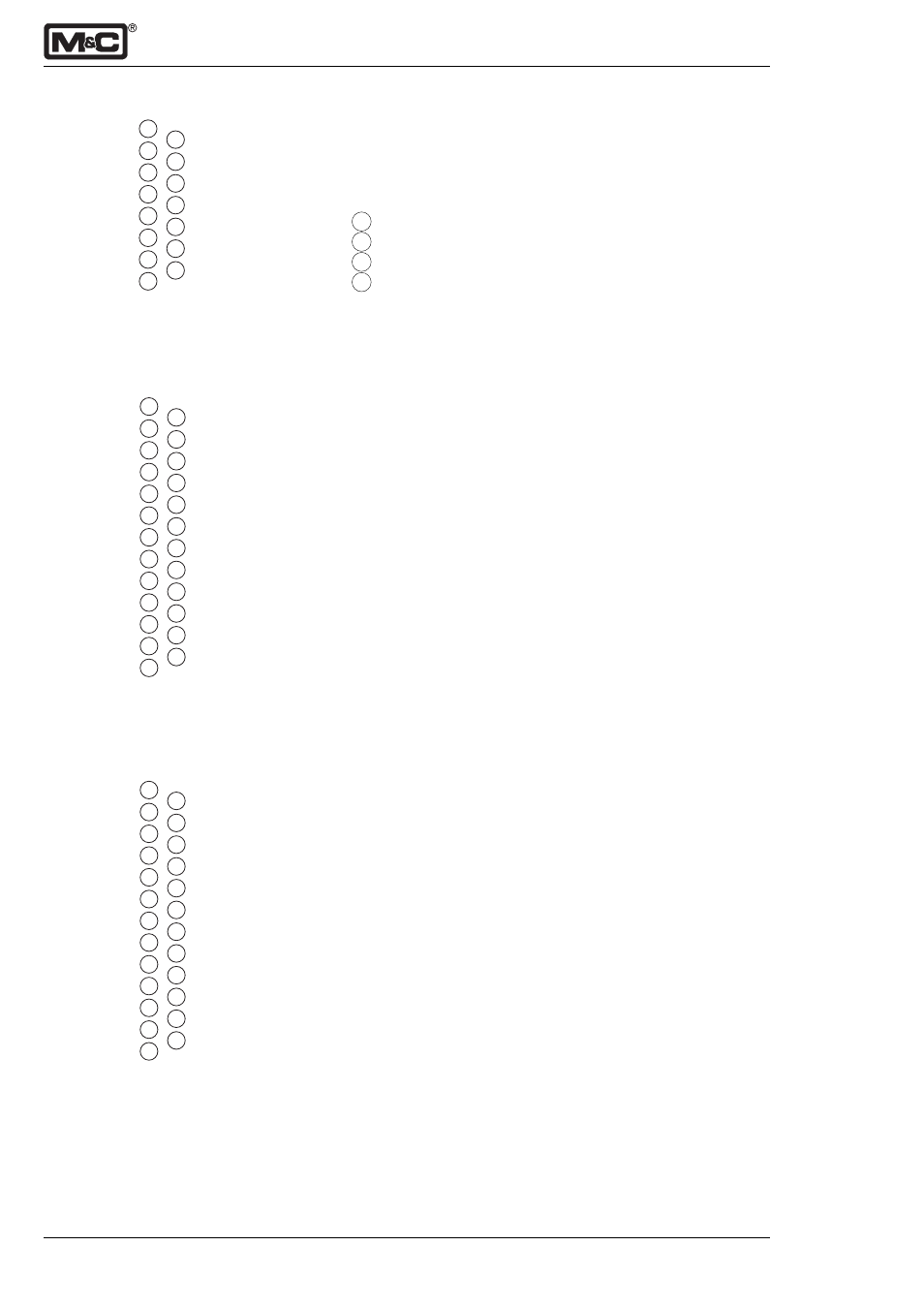
Fig. 8:
15-pole Sub-D socket X3
Fig. 9:
25-pole Sub-D plug X4
1
2
3
4
5
6
7
8
9
10
11
12
13
14
15
1
2
3
4
5
6
7
8
9
10
11
12
13
14
15
16
17
18
19
20
21
22
23
24
25
Out 4 MC
Out 3 NO
Out 2 MC
Out 1 NO
Alarm MC
Status MC
Out +24V
IN 1,2,4; GND
IN 3 (+24V)
In 1 (+24V)
In 4 (+24V)
Out 4 NO
Out 3 MC
Out 2 NO
Out 1 MC
Status NO
Out 0V
IN 3; GND
Alarm NO
In 2 (+24V)
mA +
mA +
mA +
mA +
mA -
1
2
3
4
5
6
7
8
9
10
11
12
13
14
15
16
17
18
19
20
21
22
23
24
25
24V
+0V Y1
+0V Y2
24V
+0V Y3
Option
24V
Option
Option
24V
Option
Option
24V
Option
Option
24V
Option
Option
24V
Option
Option
24V
Option
Option
24V
Fig. 10: 25-pole Sub-D socket X5
mA -
mA -
mA -
mA -
mA -
mA -
mA -