Ec control board, Figure 15, Ec30 control board – M&C TechGroup EC-30_FD Operator's manual User Manual
Page 31: 20 ec control board, Channel 2 channel 1
31
Gas sampling and gas conditioning technology
3-4.20-ME
20
EC CONTROL BOARD
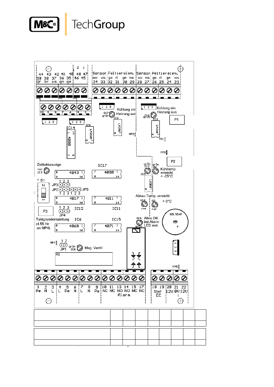
Figure 15 shows the layout of the EC30 control board (wiring diagram in appendix).
Figure 15 EC30 control board
Temperature
adjustment
(zero)
Alarm threshold
(<-25°C at MP3)
Power
Trans-
former
Solenoid
valve
Power
supply
Channel 2
Channel 1
Channel
Operating indication
Heating
Operati
o
n
T
es
t
Voltage at MP1, MP2, MP3 measured
against MP5 (V):
1
2
3
4
5
6
7
8
Corresponding temperatures in °C
+30
+20
+10
0
-10
-20
-30
-40
Voltage at MP1, MP2, MP3 measured
against MP5 (V):
1
2
3
4
5
6
7
8
Corresponding temperatures in °C
+30
+20
+10
0
-10
-20
-30
-40
See also other documents in the category M&C TechGroup Equipment:
- SP10 Operator's manual (14 pages)
- N9 KP18 Operator's manual (21 pages)
- SP2000_20SS 150 Data sheet (3 pages)
- SP3100 Data sheet (6 pages)
- PSP4000-H _C _T Data sheet (4 pages)
- SP2200-H_C_I_BB_F Data sheet (2 pages)
- SP35-H... for gas sample probe SP2000-H... Data sheet (2 pages)
- FP-BF Data sheet (2 pages)
- SP3200 Operator's manual (28 pages)
- FPF-0,1 Operator's manual (2 pages)
- PSS-10_1 Operator's manual (23 pages)
- CSS-V2 Data sheet (3 pages)
- PMA 50 EEX Operator's manual (48 pages)
- MP30 Operator's manual (18 pages)
- SP2600-H_C_I_BB_F_0,1GF190 Data sheet (3 pages)
- SR25.1_Ex Operator's manual (22 pages)
- PMA 10S Operator's manual (27 pages)
- CSS-M_W Data sheet (3 pages)
- PAS-500 Operator's manual (20 pages)
- SP2000H320_DIL... Data sheet (3 pages)
- SP3200 Data sheet (6 pages)
- FA-1_2_3,bi Operator's manual (24 pages)
- SR25 Data sheet (2 pages)
- SP3000 Data sheet (4 pages)
- PAS Series Data sheet (2 pages)
- CG Series Data sheet (2 pages)
- ECP 20-2 Data sheet (3 pages)
- MP30-EX Data sheet (2 pages)
- PSP4000-H_C_T Operator's manual (24 pages)
- DIL-U Data sheet (2 pages)
- ADS-So Data sheet (2 pages)
- VC-2-SL Operator's manual (18 pages)
- ECM-ExII Operator's manual (39 pages)
- MP12 Operator's manual (17 pages)
- FPF+ Data sheet (2 pages)
- KS 2.Ex Operator's manual (17 pages)
- PMA 50 EEX Data sheet (3 pages)
- PMA 10S Data sheet (3 pages)
- Gas Sample Probes Series SP Data sheet (2 pages)
- BA-C Operator's manual (16 pages)
- MV3_2-H Series Operator's manual (18 pages)
- VC-2-SL Data sheet (3 pages)
- FM-200K-H_FA Operator's manual (16 pages)
- SP 30-H.._EX2 Operator's manual (16 pages)
- SP2006-H280_DIL Operator's manual (35 pages)