Figure 4, Tubing of the heat exchangers, Figure 5 – M&C TechGroup EC-30_FD Operator's manual User Manual
Page 13: Timing schematic of the switching processes
13
Gas sampling and gas conditioning technology
3-4.20-ME
A decoupled compressor cooler system has a heat-insulated cooling block at a constant temperature
of +1
C. Control of the compressor is contactless done by the EC automatic control electronics and is
therefore not subject to wear. The pre-cooling stage ensures that the greater part of the condensate
has already been removed from the gas stream.
The low-temperature stages are provided with two modified jet stream EC30 heat exchangers made of
Duran glass. These are cooled down to a temperature of around -30
C by two completely independent
Peltier element cooling systems.
Stages
and
(see fig. 1) of the gas cooler work intermittently at intervals of three hours. While one
stage is in operation, the other one is automatically defrosted. All the heat exchangers are easily
accessible and are arranged in such a way that they can be removed very simply. Switching over the
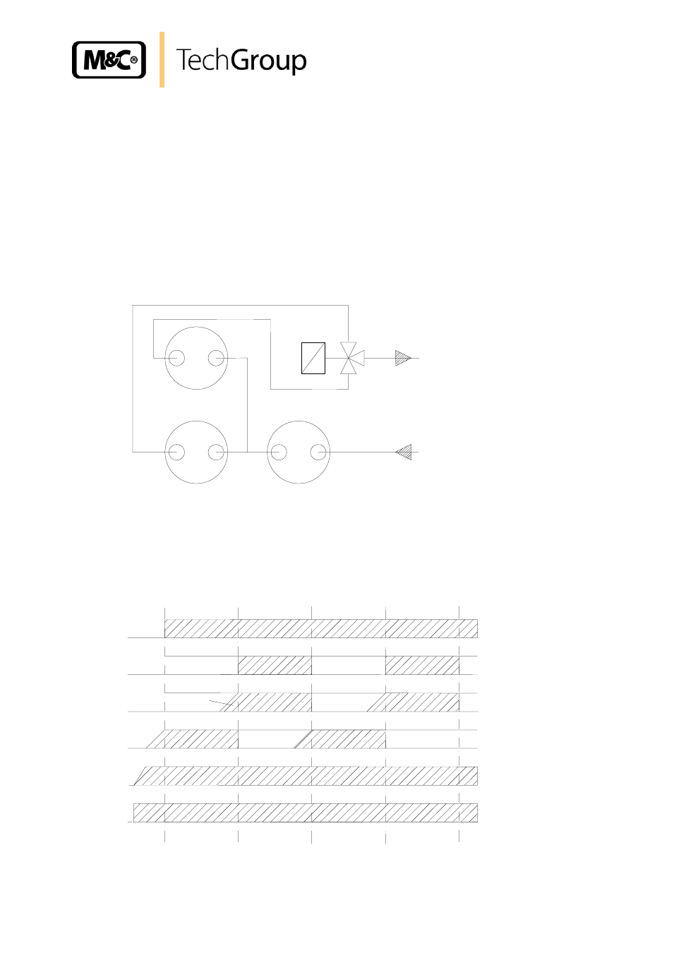
gas flow is done by a 3/2-way solenoid valve made of PVDF/Viton (see fig. 4). This arrangement
excludes any possibility of water vapour being sucked back from the low-temperature stage that is
being defrosted.
Figure 4 Tubing of the heat exchangers
The EC30 control electronic switches the solenoid valve every three hours and at the same time
carries out the alternating defrosting
process of the low-temperature heat exchangers.
Figure 5 Timing schematic of the switching processes
Solenoid valve
Channel 2
Channel 1
Temperature channel 2
Temperature channel 1
EC pre-cooler
Ambient temperature
Power OFF
Power ON, start
1 hr
3 hr
3 hr
3 hr
3 hr
Status
o.k.
Alarm
-30°C
+5°C
-30°C
+5°C
+1°C
Sample gas
IN
Sample gas
OU
T
Pre-cooling stage
Deep cooling stages