Figure 6, Position of terminal x0, Figure 7 – M&C TechGroup EC-30_FD Operator's manual User Manual
Page 17: Electrical connections
17
Gas sampling and gas conditioning technology
3-4.20-ME
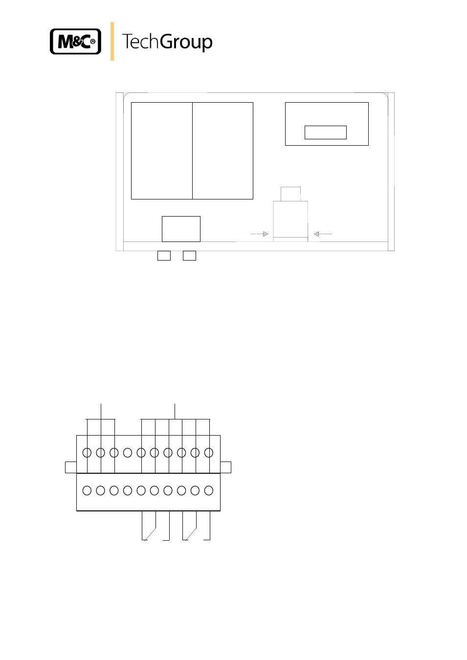
Figure 6 shows the location of the terminal X0 behind the front panel of the EC-30 casing (fig. 2).
Power supply : 230V/50Hz or 115V/60Hz (see type plate)
Status alarm : two potential free changeover contacts
Contact rating : 250V AC, 2A, 500VA or
250V DC, 2A, 50W
Figure 6 Position of terminal X0
Two PG 13,5 cable glands are provided for the cable bushings through the base plate of the cooler
casing. Power and alarms have to be connected as shown in the pin configuration in Figure 7 below:
Figure 7 Electrical connections
1
2
3
4
5
6
7
8
9
10
NC MC NO
NC MC NO
PE
N
L
X0
Power connection to
EC electronics
Alarm connection to
EC electronics
Power In
by customer
Alarm connection by
customer
EC-electronic
Pre-cooler
EC30-electronic
deep
cooler
EC30 power supply
Terminal X0
Solenoid valve
Sample gas switching
from deep
cooling stage
from deep
cooling stage
2 x PG 13,5
- SP10 Operator's manual (14 pages)
- N9 KP18 Operator's manual (21 pages)
- SP2000_20SS 150 Data sheet (3 pages)
- SP3100 Data sheet (6 pages)
- PSP4000-H _C _T Data sheet (4 pages)
- SP2200-H_C_I_BB_F Data sheet (2 pages)
- SP35-H... for gas sample probe SP2000-H... Data sheet (2 pages)
- FP-BF Data sheet (2 pages)
- SP3200 Operator's manual (28 pages)
- FPF-0,1 Operator's manual (2 pages)
- PSS-10_1 Operator's manual (23 pages)
- CSS-V2 Data sheet (3 pages)
- PMA 50 EEX Operator's manual (48 pages)
- MP30 Operator's manual (18 pages)
- SP2600-H_C_I_BB_F_0,1GF190 Data sheet (3 pages)
- SR25.1_Ex Operator's manual (22 pages)
- PMA 10S Operator's manual (27 pages)
- CSS-M_W Data sheet (3 pages)
- PAS-500 Operator's manual (20 pages)
- SP2000H320_DIL... Data sheet (3 pages)
- SP3200 Data sheet (6 pages)
- FA-1_2_3,bi Operator's manual (24 pages)
- SR25 Data sheet (2 pages)
- SP3000 Data sheet (4 pages)
- PAS Series Data sheet (2 pages)
- CG Series Data sheet (2 pages)
- ECP 20-2 Data sheet (3 pages)
- MP30-EX Data sheet (2 pages)
- PSP4000-H_C_T Operator's manual (24 pages)
- DIL-U Data sheet (2 pages)
- ADS-So Data sheet (2 pages)
- VC-2-SL Operator's manual (18 pages)
- ECM-ExII Operator's manual (39 pages)
- MP12 Operator's manual (17 pages)
- FPF+ Data sheet (2 pages)
- KS 2.Ex Operator's manual (17 pages)
- PMA 50 EEX Data sheet (3 pages)
- PMA 10S Data sheet (3 pages)
- Gas Sample Probes Series SP Data sheet (2 pages)
- BA-C Operator's manual (16 pages)
- MV3_2-H Series Operator's manual (18 pages)
- VC-2-SL Data sheet (3 pages)
- FM-200K-H_FA Operator's manual (16 pages)
- SP 30-H.._EX2 Operator's manual (16 pages)
- SP2006-H280_DIL Operator's manual (35 pages)