4 fault messages – Toshiba G8000 User Manual
Page 74
66
G8000 Series Installation and operation Manual
15.4 Fault Messages
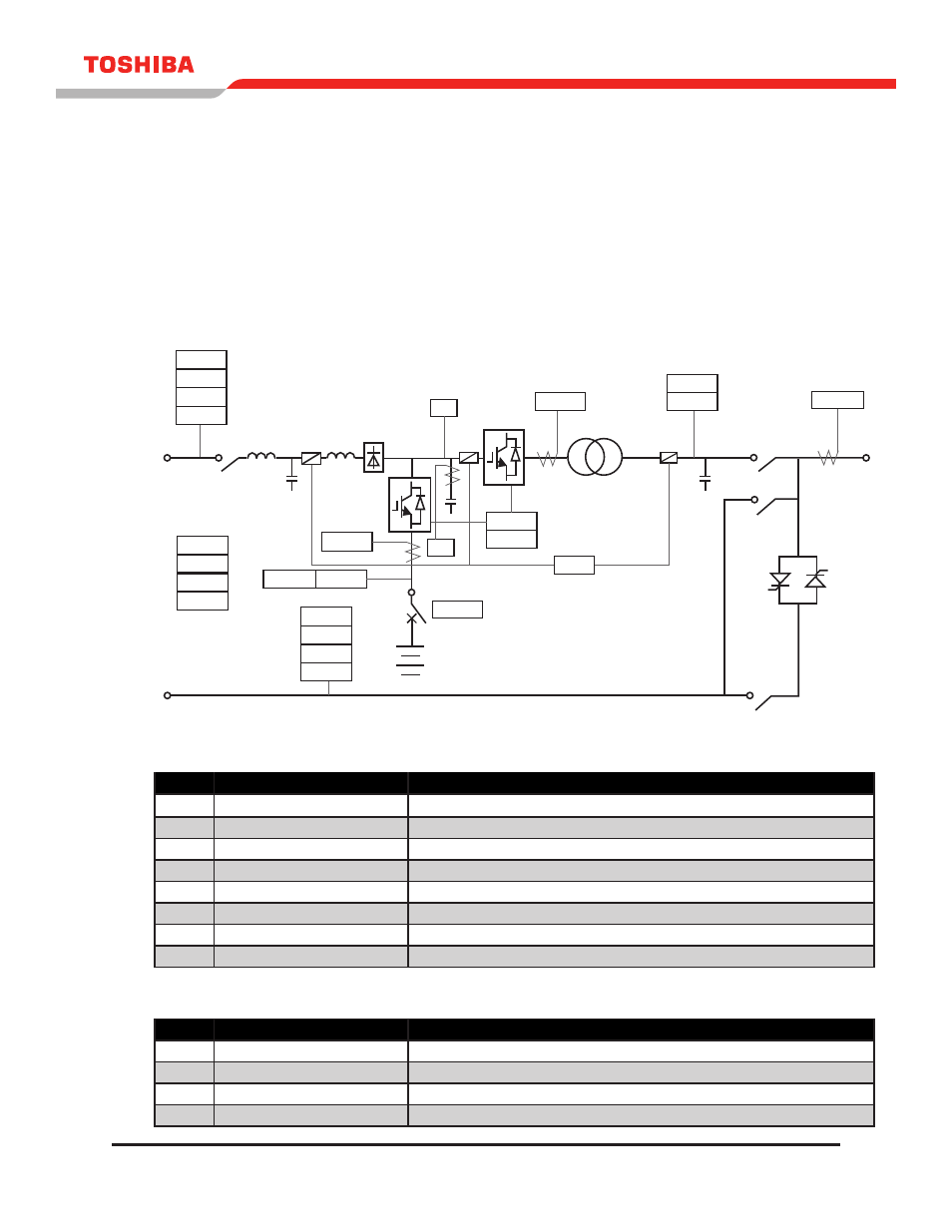
Figure 15.4 show the locations for fault detection. Tables 15.3 through 15.7 gives details for the fault and
warning messages referred to in section “Fault Data Screen.” The “item” code associated with each fault
or warning message may be used to determine the physical location of the fault or warning by referring
to Figure 15.4. The UPS unit may be shipped with different protective configurations from the standard
shown in Figure 15.4, if specified by the customer. See the protective configuration indicated on the single
line diagram for each UpS.
FIGURE 15.4 - PROTECTIVE DETECTOR LOCATIONS
TABLE 15.3 - FAULT (TRIP)
ITEM
LCD MESSAGE INDICATION
DESCRIPTION
26
OVER HEAT
HIGH TEMP IN THE CABINET.
30ST
(NO INDICATION)
AN ERROR OCCURRED IN THE MAIN CONTROL MICROPROCESSOR (CPU).
48
STARTUP ERR
STARTUP WAS NOT COMPLETED WITHIN THE NORMAL TIME FRAME.
5E
EMG.STOP
AN EMERGENCY STOP WAS ACTIVATED VIA THE EXTERNAL CONTACT.
71F
FUSE BLOWN
RECTIFIER, DC, OR INVERTER MAIN CIRCUIT FUSE BLOWN.
76
DC OC
DC OVER-CURRENT - EXCESSIVE CURRENT IN DC CIRCUIT.
80B2
BATT. UV
BATTERY VOLTAGE IS BELOW CUTOFF VOLTAGE.
80PS
CONT. PS. ERR
THE CONTROL POWER SUPPLY VOLTAGE FAILED.
TABLE 15.4 - WARNING – 1 (CONVERTER STOP/INPUT POWER ERROR)
ITEM
LCD MESSAGE INDICATION
DESCRIPTION
27S
AC I/P UV
AC INPUT UNDERVOLTAGE - AC INPUT VOLTAGE IS TOO LOW.
47S
AC PHASE ERR
AC INPUT PHASE ROTATION ERROR.
59S
AC I/P OV
AC INPUT OVERVOLTAGE - AC INPUT VOLTAGE IS TOO HIGH.
95S
I/P FREQ. ERR
AC INPUT FREQUENCY ERROR.
47S
59I
51I
48
30ST
80PS
5E
59S
27S
95S
80B1
76C
30U
26B
80B2
271
83BF
49
95C
27C
47C
59C
Inverter
83MC
83MC1
45
76
Battery
Chopper
52R
26
71F