Toshiba G8000 User Manual
Page 43
35
G8000 Series Installation and operation Manual
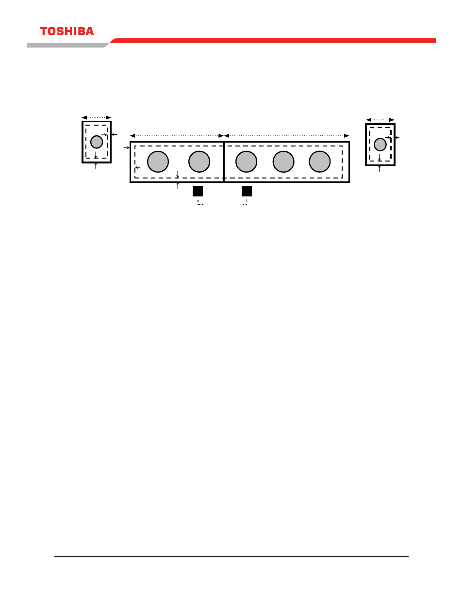
Figure 11.9 shows the four (4) cable knockout plates provided at the top of the 300 kVA UpS. Seven (7)
holes must be punched during installation. The dashed rectangle indicates the UpS opening behind the
knockout plates.
FIGURE 11.9 - TERMINAL KNOCKOUT PLATES FOR THE 300 KVA UPS
G8000 Series Installation Manual
32
Figure 11.6 shows the four (4) cable knockout plates provided at the top of the 300kVA UpS. Six (7)
holes must be punched during installation. The dashed rectangle indicates the UpS opening behind the
knockout plates.
FIGURE 11.6 - CABLE KNOCKOUT PLATES (300kVA)
0.8”
0.4”
4” Dia.
0.6”
1.5”
2“ Dia.
0.6”
2“ Dia.
plate #2
plate #3
plate #1
plate #4
GROUND WIRE
AC INPUT
BYPASS
AC OUTPUT
CONTROL WIRES
BATTERY
-
+
PLATE #3
PLATE #2
PLATE #4
PLATE #1
-
+
- Power Inverter (15 pages)
- 1800 (6 pages)
- TOSVERT VF-S11 (68 pages)
- Uninterruptible Power System G9000 (104 pages)
- Density (Consistency) Meter LQ500 (9 pages)
- MBSB80-225-43 (1 page)
- TOSNIC-7000S (53 pages)
- 1600EP Series (3 pages)
- 1500 (32 pages)
- TOSVERT VF-FS1 Series (16 pages)
- 4200FA XT1 (1 page)
- G3 Plus Pack (4 pages)
- Tosvert VF-A5 (149 pages)
- 1600 Series (3 pages)
- G9000 (100 pages)
- TEC EO1-33030 (54 pages)
- 1000 Series (2 pages)
- 1500 Plus (31 pages)
- G8000MM (6 pages)
- VT130G1 (99 pages)
- 4200FA Series (2 pages)
- VF-PS1 (10 pages)
- GX7 Series (6 pages)
- 4200FA XT (1 page)
- RMTI-EMD-HT (2 pages)
- W7 Series (6 pages)
- HX7 (6 pages)
- PDP002Z (18 pages)
- RELIABILITY IN MOTION 1700 (39 pages)
- 1700 Series (2 pages)
- G3 TOSVERT-130 (62 pages)
- B-852-TS12-QP (55 pages)
- 1000 (4 pages)
- E3 (7 pages)
- Adjustable Speed Drive H3 (122 pages)
- 55611-001 (2 pages)
- Black Gold Series (2 pages)
- Dura-Bull TX (6 pages)
- Current Relay RC803A-HP1 (19 pages)
- 1800 SERIES (2 pages)
- Isolated-Redundant UPS System (2 pages)
- Tosvert VF-AS1 (312 pages)
- RELIABILITY IN MOTION 1000 (54 pages)
- REMOTE-D (2 pages)
- 15-80KVA (2 pages)