Signal parameters on ils display – Procom VOR/ILS Analyzer EVS200 User Manual
Page 29
VOR/ILS Analyzer EVS200
0796.1800.02
E-8
20
Chapter 3: Operation
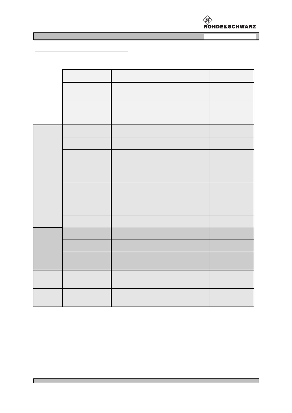
Signal parameters on ILS display
Following signal parameters are indicated on the display:
display indication
description
measuring value
FREQ. (MHZ)
receiver frequency in MHz (numerical) and
bargraph center frequency indication in kHz
MHz
LEVEL (dBm)
receiver signal in dBm (numerical) and
bargraph indication (the lower bargraph
shows the set squelch threshold)
dBm
DISPL 1/2
AM-MOD.(90HZ)
AM modulation depth (90 Hz)
%
AM-MOD.(150HZ)
AM modulation depth (150 Hz)
%
DDM
differences in depth of modulation
DDM-value
(non-dimension value)
µ
A
%
SDM
total modulation factor
SDM-value
(non-dimension value)
µ
A
%
PHI (90/150)
phase shift (90 Hz/150 Hz)
degree
DISPL 2/2
ID AF-FREQ.
AF frequency (1020 Hz)
Hz
ID AM-MOD.
AM modulation depth of AF frequency
%
VOICE AM-MOD.
AM modulation depth in the range of
300 to 3000 Hz
%
Y / t Setup
Range 1 to 4
XY value scaling in localizer /
glideslope mode at DSP-Out.
%
STORE
DDM menu
Locations 1 to 120
DDM/SDM results