Procom VOR/ILS Analyzer EVS200 User Manual
Page 19
VOR/ILS Analyzer EVS200
0796.1800.02
E-8
10
Chapter 2: Preparation for Operation
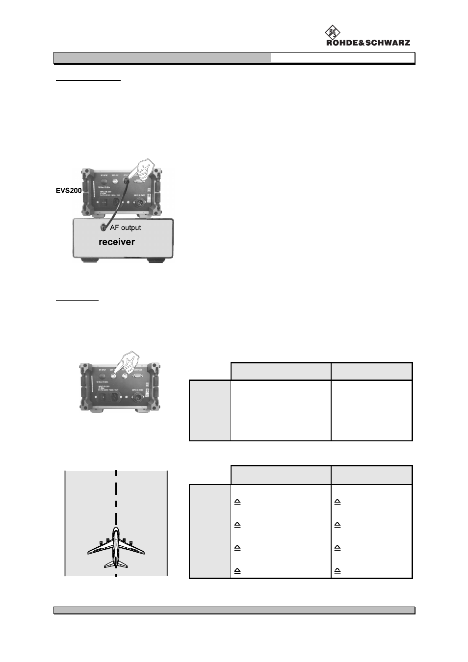
External AF input
Via the AF input (AF-EXT) at the rear side the unit can be fed with an AF signal for further analysis of
typical AF parameters (e.g. level, frequency). This is very applicable for receivers which cannot per-
form AF analysis.
input level:
approx.: 1 to 2 V
rms
/ 50
Ω
e.g. VOR/ILS Analyzer
Þ=
external receiver
Connection AF-EXT of the VOR/ILS Analyzer EVS200 with
the AF output of an external receiver
DSP output
On the DSP-OUT at the rearside e.g. a XY-tracer can be connected. The scaling of the XY values
can be set for any mode (localizer/glideslope) in the setup (DDM Y / t-RANGE) or in ILS-Mode
(Y / t-SETUP).
output signals in VOR- and ILS-Mode:
ILS-Mode
VOR-Mode
Display 1
normalized DDM-values
(DC-voltage)
Range 1 to 4
no output
Display 2
voice-frequency
(300 to 3000 Hz)
voice-frequency
(300 to 3000 Hz)
scaling in the setup:
Localizer
Glideslope
Range 1
Range 2
Range 3
Range 4
0.0
±
25%
0
±
0.25 DDM
0.0
±
2.5%
0
±
0.025 DDM
0.0
±
2.58%
0.0
±
0.0258 DDM
0.0
±
50%
0.0
±
0.5 DDM
0.0
±
50%
0.0
±
0.5 DDM
0.0
±
5%
0.0
±
0.05 DDM
8.75
±
5%
0.0875
±
0.05 DDM
17.5 +5%
0.175 +0.05 DDM
(corresponding
DC voltage)
(0 V
±±±±
5 mV)
0 DDM
(1 V
±±±±
5 mV)