Dc connection – Procom VOR/ILS Analyzer EVS200 User Manual
Page 17
VOR/ILS Analyzer EVS200
0796.1800.02
E-8
8
Chapter 2: Preparation for Operation
DC connection
Only connect the unit when the minus pole of the battery
is connected to vehicles ground (GROUND
)!
input voltage: 9 to 15 VDC
Assembling the FO Cable Jack
Finish the supplied FO cable jack (0018.6700) as following with commercial PVC cables.
cable specification
PVC wiring performance according VDE 0281
wire cross section 1.0 mm
2
or more
colour RED for +VDC
colour BLUE for ground(
)
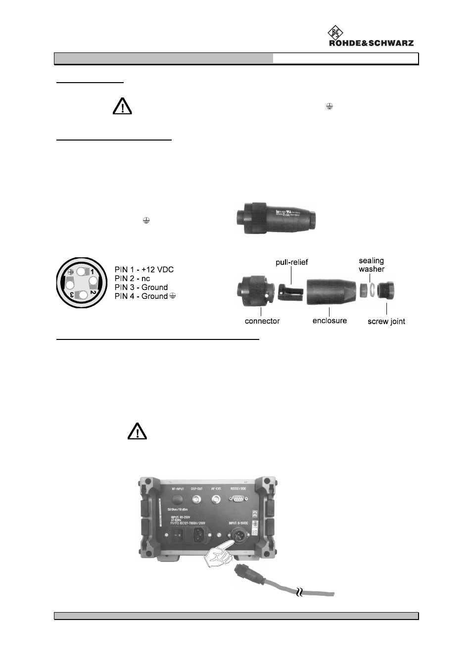
FO cable jack
order no.:
0018.6700
Pin connection of the FO cable jack
Assembling the FO cable jack
Finishing and connection to the Vehicle Board Supply
Strip the cable end ca. 8 mm and mount multicore.
Draw the cable through the enclosure and connect it according to the above pin connection of
the FO cable jack.
Fit the pull-relief and assemble the FO cable jack.
Connect the cable to the vehicle board supply.
When connecting the finished cable to the 12-VDC vehicle
board supply there is to perform a protection by a cable fuse
(T2.0 A) or a fuse on board!
Connect and lock the FO cable jack in the VDC input at the rear of the unit.