Setup-mode – Procom VOR/ILS Analyzer EVS200 User Manual
Page 23
VOR/ILS Analyzer EVS200
0796.1800.02
E-8
14
Chapter 3: Operation
SETUP-Mode
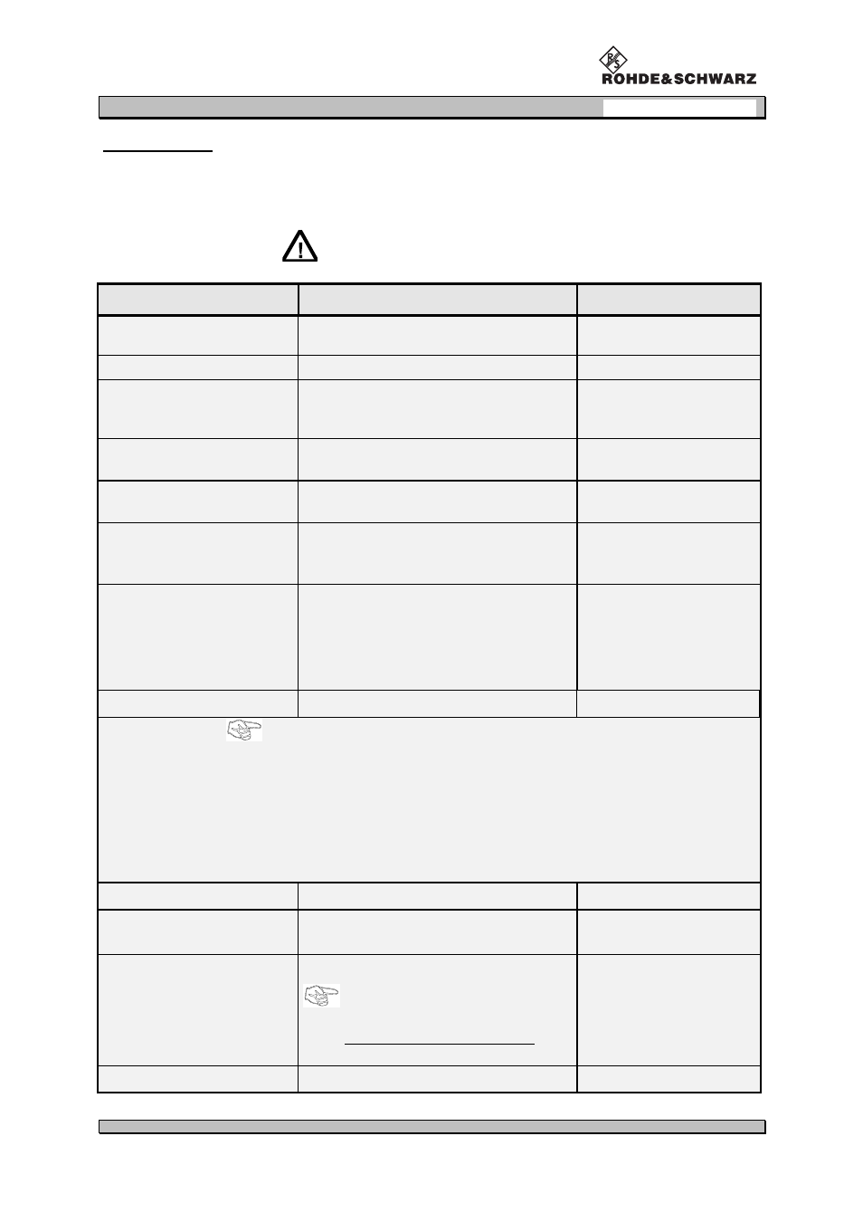
In the following table all possible parameters are listed and its functions are described. Furthermore all
possible setting values per parameter are shown. Next a sequence chart of the operating instructions
in the SETUP mode is following.
Changes in the SETUP can be saved
with the softkey "SAVE".
parameter
description
setting value
RS232 BAUDRATE
baud rate setting
1200, 2400, 4800,
9600, 19200
VOR ANGLE-RESOLUTION
BEARING-angle resolution
0,01° / 0,05°
DDM/SDM AVG-FACTOR
factor for determining the number of
measurements which form the arithmeti-
cal average
1, 2, 4, 8, 16, 32, 64
DDM Y / t-RANGE [LOC]
XY value scaling in localizer mode at
DSP-OUT (refer to page 10 DSP output)
RNG.1 to RNG.4
DDM Y / t-RANGE [GS]
XY value scaling in glideslope mode at
DSP-OUT (refer to page 10)
RNG.1 to RNG.4
AF-INPUT-SOURCE
AF selection for valuation
INT = internal AF
EXT = external AF
via AF-EXT-input
STARTUP mode
startup mode setting at switching on the
unit
VOR
(VOR mode)
ILS
(ILS mode)
BCN
(Beacon mode)
SPEC
(Spectrum mode)
LEVEL
(
∆∆∆∆
level mode)
SQUELCH
on/off switching squelch
ON / OFF
setting valid for:
-
∆
level mode
-
ILS mode
-
VOR mode
When the setting is "ON" an automatical quiet tuning is performed as soon
as the threshold level < the receiver level is.
When setting is "OFF" no quiet tuning will be performed.
DISPLAY ILLUM
display brightness setting
OFF
⇐
1 to 6
Þ
MAX
DDM/SDM DIMENSIONS
value of DDM/SDM indication
µ
A / % / 1
(1= value without dimension)
DISPLAY-INTERVALL
indication interval time
setting is only valid for display indi-
cation
.
1
to
8
approx. 0.4 s to approx. 1.8 s
1 to 8
TUNING-STEP
tuning step rate setting
5 / 25 / 50 / 100
(kHz)