Connecting the cables, Updating the server configuration, Connecting – Lenovo 3797 User Manual
Page 117: Cables, Updating, Server, Configuration
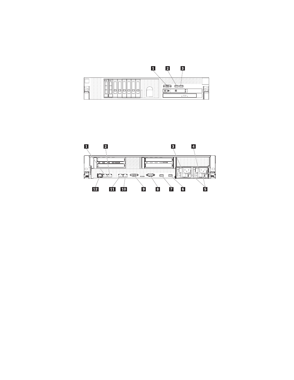
Connecting
the
cables
The
following
illustrations
show
the
locations
of
the
input
and
output
connectors
on
the
front
and
rear
of
the
server.
Front
view
1
Video
connector
2
USB
1
connector
3
USB
2
connector
Rear
view
1
Ethernet
3
(optional)
7
USB
3
2
Ethernet
4
(optional)
8
Serial
3
Power
supply
1
9
Video
4
Power
supply
2
10
Ethernet
2
5
Power
cord
connectors
11
Ethernet
1
6
USB
4
12
Systems-management
(Ethernet)
You
must
turn
off
the
server
before
you
connect
or
disconnect
cables
from
the
server.
Exception:
in
order
to
view
the
error
LEDs
inside
the
server,
you
must
leave
the
power
cables
connected
to
the
power
supplies.
See
the
documentation
that
comes
with
any
external
devices
for
additional
cabling
instructions.
It
might
be
easier
for
you
to
route
cables
before
you
connect
the
devices
to
the
server.
Cable
identifiers
are
printed
on
the
cables
that
come
with
the
server
and
optional
devices.
Use
these
identifiers
to
connect
the
cables
to
the
correct
connectors.
If
the
server
comes
with
an
installed
operating
system,
see
the
documentation
that
comes
with
the
operating
system
for
additional
cabling
instructions.
Updating
the
server
configuration
When
you
start
the
server
for
the
first
time
after
you
add
or
remove
an
internal
device,
external
SAS
device,
or
USB
keyboard
or
mouse,
you
might
receive
a
message
that
the
configuration
has
changed.
The
Server
Configuration
and
Boot
Chapter
5.
Installing
optional
devices
and
replacing
customer
replaceable
units
101