14 system panel connector, Table 4-17: com6 serial port connector pinouts, Table 4-17 – Intel iEi Motherboard A300 User Manual
Page 62: A300 motherboard, Page 47
A300 Motherboard
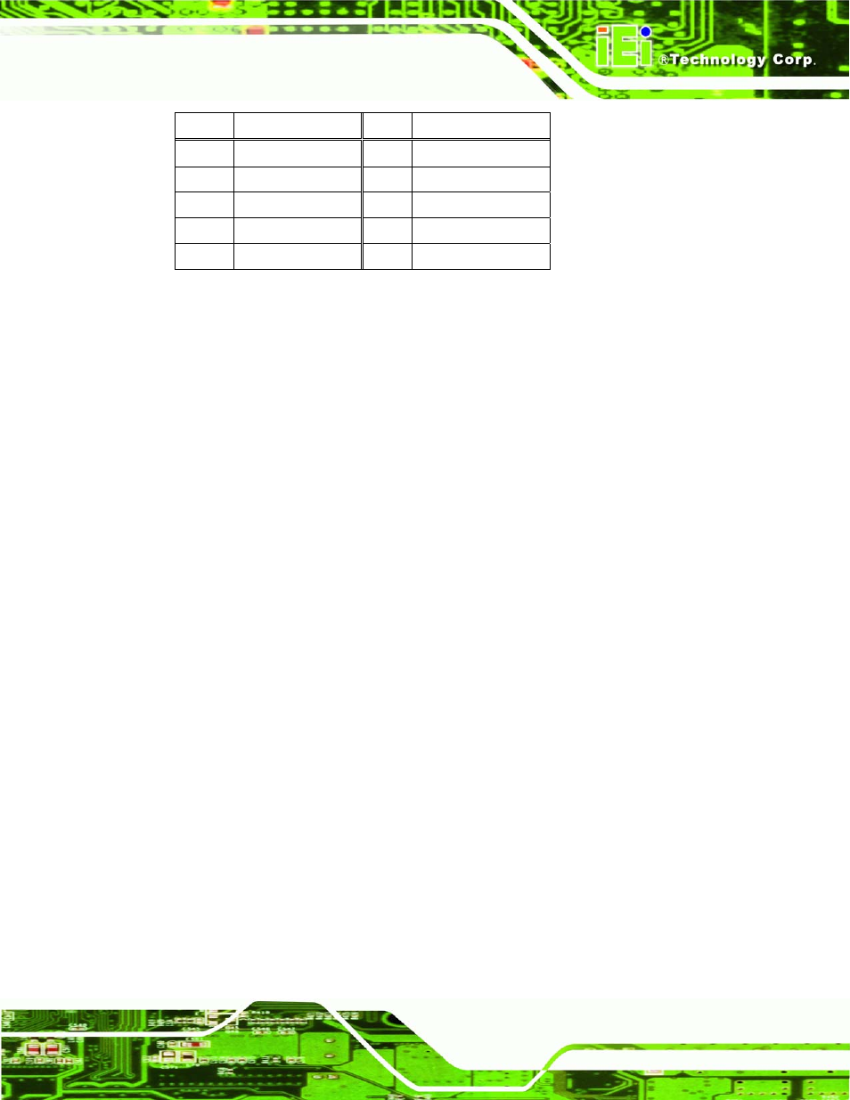
PIN NO. DESCRIPTION
PIN NO. DESCRIPTION
1 DCD6
2
DSR6
3 RX6
4
RTS6
5 TX6
6
CTS6
7 DTR6
8
RI6
9 GND
10
GND
Table 4-17: COM6 Serial Port Connector Pinouts
4.2.14 System Panel Connector
CN Label:
CN12
CN Type:
12-pin header (2x6)
CN Location:
CN Pinouts:
The front panel connector connects to several external switches and indicators to monitor
and control the motherboard. These indicators and switches include:
Power LED
ATX Power button
Reset button
HDD LED
Speaker
Page 47
See also other documents in the category Intel Hardware:
- 41210 (64 pages)
- 8xC251TQ (20 pages)
- ENTERPRISE PRINTING SYSTEM (EPS) 4127 (84 pages)
- U3-1L (20 pages)
- 80960HA (104 pages)
- X58 (54 pages)
- ESM-2850 2047285001R (91 pages)
- ATOM US15W (54 pages)
- D915GVWB (4 pages)
- XP-P5CM-GL (28 pages)
- AX965Q (81 pages)
- CORETM 2 DUO MOBILE 320028-001 (42 pages)
- CV700A (63 pages)
- 80C188EA (50 pages)
- X25-M (28 pages)
- XP-P5IM800GV (26 pages)
- IB868 (60 pages)
- D865GVHZ (88 pages)
- IB865 (64 pages)
- Altera P0424-ND (1 page)
- 8086-2 (30 pages)
- IXDP465 (22 pages)
- IWILL P4D (104 pages)
- GA-8I955X PRO (88 pages)
- FSB400 (PC2100) (96 pages)
- D845GLAD (4 pages)
- NAR-3041 (1 page)
- 87C196CA (136 pages)
- G52-M6734XD (74 pages)
- A96134-002 (10 pages)
- Express Routers 9000 (8 pages)
- 82540EP (45 pages)
- D865GLC (94 pages)
- IB850 (69 pages)
- MB898RF (62 pages)
- Arima LH500 (78 pages)
- V09 (33 pages)
- I/O Processor (22 pages)
- M600 (110 pages)
- SE7520JR2 (63 pages)
- SERVER BOARD S5520HCT (30 pages)
- Extensible Firmware Interface (1084 pages)
- GA-8IPXDR-E (70 pages)
- D845EBG2 (4 pages)
- AW8D (80 pages)