I/o (x)apic arbitration id register format -50, I/o (x)apic rte format -50, 4 i/o (x)apic rte (10h-8fh) – Intel 460GX User Manual
Page 70
Register Descriptions
2-50
Intel® 460GX Chipset Software Developer’s Manual
2.6.3.4
I/O (x)APIC RTE (10h-8Fh)
The interrupt RT has a dedicated entry for each interrupt input pin. Software can individually
choose the interrupt vector number for input pins. For each individual pin, the operating system can
also specify the signal polarity (low-active or high-active), whether the interrupt is signaled as
edges or levels, as well as the destination and delivery mode of the interrupt. The information in the
RT is used to generate the inter-(x)APIC message upon assertion/deassertion of the interrupt pin.
The PID’s version register contains the number of entries in the interrupt RT. Offsets 10h through
8Fh are used for the interrupt RT. Each entry in the table is 64-bits. The format of each entry is
described in
.
Note:
The interrupt RT is shared between SAPIC and APIC modes. Some of the fields have different
meanings in the two modes as indicated in Columns 2 and 3. The PID implements only those bits
that have valid functional fields associated with them. Reserved bits cannot be written and will
return 0s when read.
Since each RTE is 64 bits wide, it must be accessed using two 32-bit memory read or write
operations to consecutive dword-aligned addresses. The lower half of the entry, bits 31 through 0,
is located at the even offset (such as 10h) and the upper half of the entry, bits 63 through 32, is
located at the odd offset (such as 11h). While programming the RTEs, it is recommended that the
lower half be programmed first, followed by the upper half.
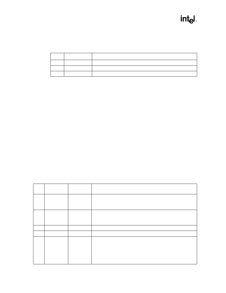
Table 2-9. I/O (x)APIC Arbitration ID Register Format
Register Offset: 02h
Default Value: [00000000h]Attribute: Read-Only
Bit(s)
Name
Description
31:28
Reserved
These four bits are reserved.
27:24
ARBID
APIC Arbitration ID.
23:0
Reserved
These 24 bits are reserved.
Table 2-10. I/O (x)APIC RTE Format
Register Offset: 10-8Fh
Default Value: Undefined except mask bit is 1Attribute: Read/Write
Bit(s)
SAPIC Mode
Name
APIC Mode
Name
Description
63:56
DEST ID
DEST ID
This field contains an (x)APIC ID. Local (x)APIC units receiving an interrupt
message compare the DEST ID and DEST EID fields to the corresponding
fields in their LID registers to determine if the interrupt is to be serviced by
them.
55:48
DEST EID
Reserved
This field contains the extended (x)APIC ID. Local (x)APIC units receiving an
interrupt message will use this field along with the DEST ID field to determine if
the interrupt is to be accepted by them. This field is not used during APIC
mode.
47:32
Reserved
Reserved
These 16 bits are reserved
31:18
Reserved
Reserved
These 14 bits are reserved
17
FLUSHEN
FLUSHEN
This bit controls the flushing of the I/O buffer on a per-interrupt basis.
A 0 indicates that the buffer must be flushed before the interrupt is sent to the
local (x)APIC. This setting will cause the hardware flush control signals to be
used.
A 1 indicates that the buffer does not need to be flushed before the interrupt is
sent out to the local (x)APIC. This setting will cause the hardware flush control
signals to be ignored.