Grizzly G0623X3 User Manual
Page 29
Model G0623X/G0623X3 (Mfg. Since 5/12)
-27-
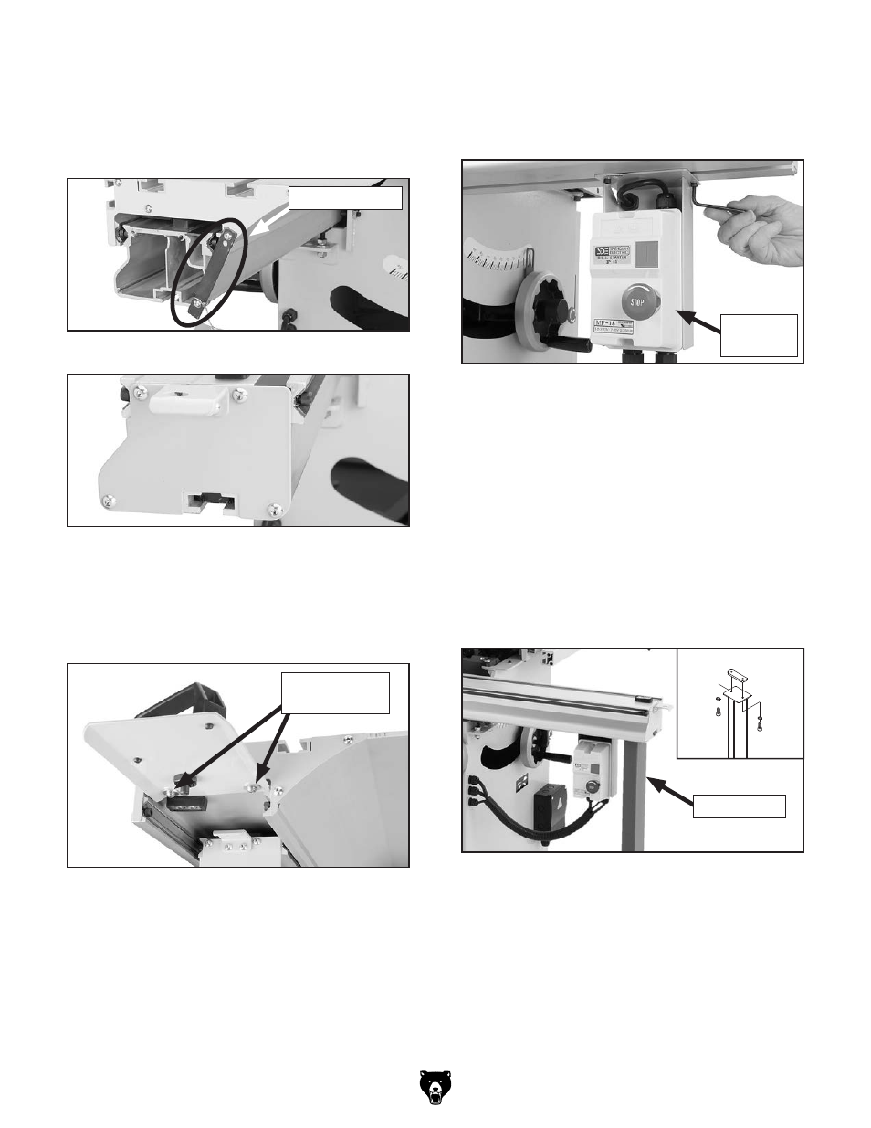
26. thread two m5-.8 x 12 cap screws with 5mm
lock washers through the switch bracket and
into the sliding table base, and tighten the
cap screws (see
figure 35).
25. attach the sliding table handle, as shown in
figure 34, with two button head screws and
flat washers, using the premounted hard-
ware.
24. remove the shipping brace from the sliding
table (
figure 32), then install the sliding table
end cover over the fixed part of the sliding
table end, as shown in
figure 33, using the
premounted hardware.
figure 32. sliding table shipping brace.
shipping brace
figure 33. sliding table end cover installed.
figure 34. sliding table handle attached to end
of sliding table.
button head
Cap screws
27. thread the feet all the way into the bottom of
the support legs. do Not remove the hex
nuts pre-installed on the bottom of the feet,
since they will be used after the legs are
installed.
28. thread two m10-1.5 x 30 cap screws and
10mm lock washers through each support
leg and part way into the t-slot plates for
the legs, slide the t-slot plates into the both
ends of the sliding table base, and tighten the
mounting cap screws (see
figure 36).
figure 35. magnetic switch installed.
magnetic
switch
figure 36. support leg installed (1 of 2 shown).
support leg