Grizzly G0623X3 User Manual
Page 26
-24-
Model G0623X/G0623X3 (Mfg. Since 5/12)
9. level the top of the extension tables even
with the top of the cast iron table.
using a straightedge as a guide (
figure 20),
adjust the leveling cap screws to align the top
of extension tables with the top of the cast
iron table. tighten the hex nuts on the level-
ing cap screws against the extension table
to lock the cap screws when the tables are
aligned.
figure 20. extension wings mounted and even
with cast iron table.
10. mount the rip fence scale to the large exten-
sion table and cast iron table (
figure 21)
using three 6mm hex nuts, lock washers, flat
washers, two m6-1 x 16 hex bolts, and one
m6-1 x 25 hex bolt. (the longer hex bolt is
used in the cast iron table.) secure the scale
height so it is even with the table tops.
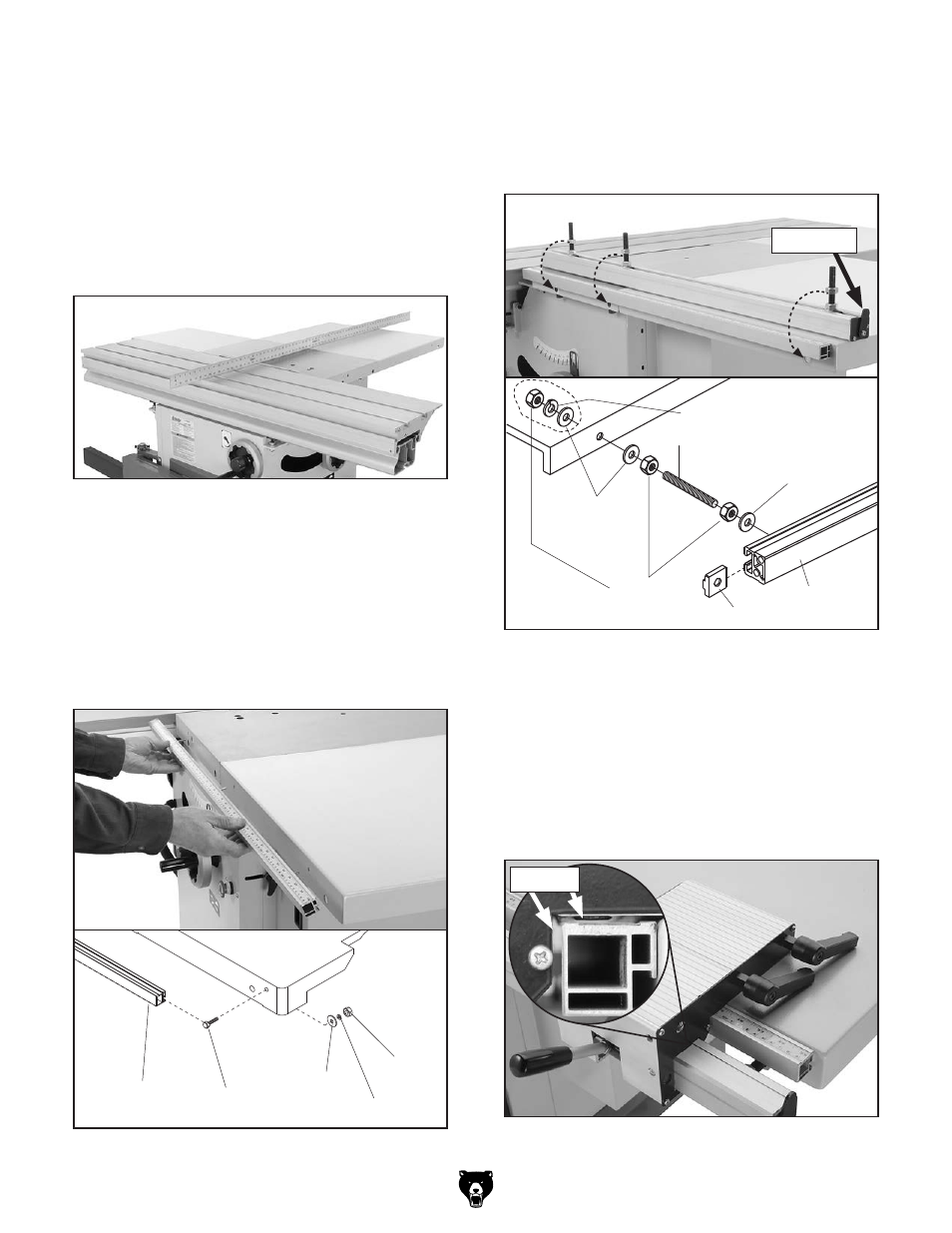
11. mount the rip fence rail as shown in figure
22. make sure the black tab is toward the
back end of the saw. adjust the hex nuts so
the gap between the rail and tables is even,
but leave the rail slightly loose for now.
figure 21. mounting rip fence scale.
Scale
Hex Bolt
Hex Nut
Lock Washer
Flat Washer
Table
12. slide the rip fence base on the rail, and check
the spacing between the rip fence base and
scale bar (see
figure 23). there should be
a minimum of
1
⁄
8
" of space between the scale
bar and the fence base. adjust the mount-
ing position of the rip fence rail to create this
space evenly along the length of the scale
bar, then tighten the rail mounting nuts.
figure 23. fence base installed; spacing
between fence base and scale bar.
spacing
figure 22. rip fence rail mounting.
Rail
T-Nut
M12-1.75
Hex Nut
Stud M12-1.75 x 90
12mm
Flat Washer
12mm Flat Washer
12mm Lock Washer
black tab