Ac power diagrams, Details for ac mating connector, Figure 3-8 – Adept i600 Cobra User Manual
Page 33: Figure 3-9
Connecting 24 VDC Power to Robot
Adept Cobra i600/i800 Robot User’s Guide, Rev G
33
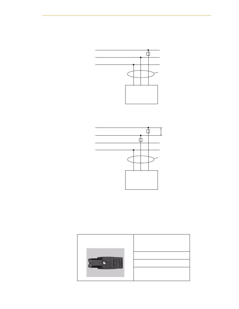
AC Power Diagrams
Figure 3-8. Typical AC Power Installation with Single-Phase Supply
Figure 3-9. Single-Phase Load across L1 and L2 of a Three-Phase AC Supply
Details for AC Mating Connector
The AC mating connector is supplied with each system. It is shipped in the Accessory Kit.
The supplied plug is internally labeled for the AC power connections (L, E, N).
Table 3-6. AC Mating Connector Details
AC Connector details
AC in-line power plug,
straight, female, screw
terminal, 10 A, 250 VAC
Qualtek P/N 709-00/00
Digi-Key P/N Q217-ND
Adept P/N 02710-000
E
E
N
L
L
F1 10 A
Adept Cobra
s600/s800 and
i600/i800 Robots
1 Ø 200–240 VAC
User-Supplied
AC Power Cable
Note: F1 is user-supplied, must be slow blow.
1 Ø
200–240 VAC
L = Line
N = Neutral
E = Earth Ground
N
20 A
E
E
N
L3
L
L1
L2
F5 10 A
F4 10 A
Adept Cobra
s600/s800 and
i600/i800 Robots
1 Ø 200–240 VAC
User-Supplied
AC Power Cable
Note: F4 and F5 are user-supplied, must be slow blow.
3 Ø
200–240 VAC
L = Line 1
N = Line 2
E = Earth Ground
200–240 VAC