Rear panel – HP TC2120 User Manual
Page 9
3
Chapter 1
Controls and Indicators
Rear Panel
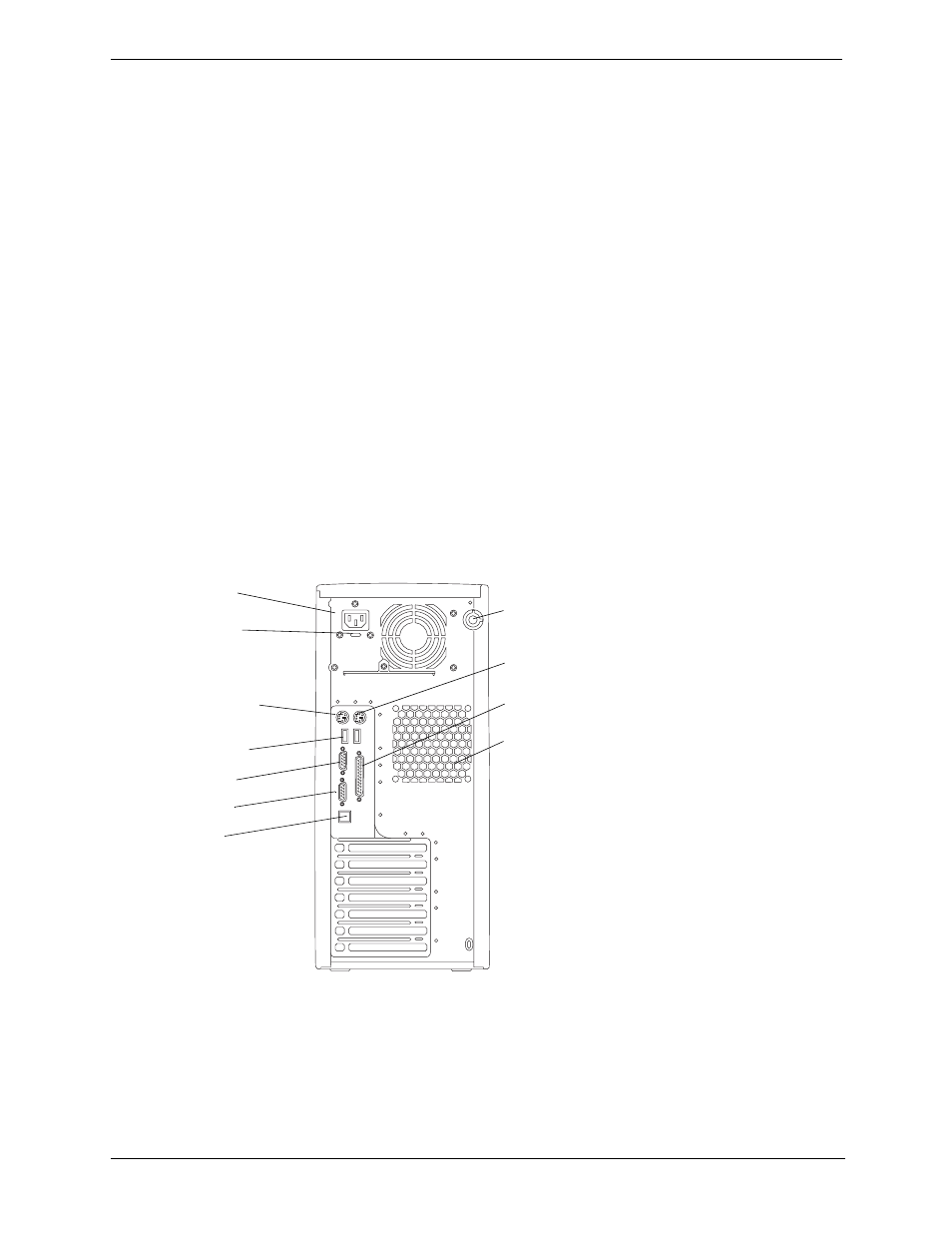
The ports, connectors, switches, and other related items at the rear of the Server are listed below and shown in
Figure 1-3.
• The power connector accepts a standard power cable to connect the hp server tc2120 with the site power
source.
• The input voltage selector switch is used to adapt the power supply to the input line voltage. The two switch
settings are 115 volts or 230 volts.
• The mouse port accepts a standard mouse with a PS/2 connector.
• The keyboard port accepts a standard keyboard with a PS/2 connector.
• Two USB ports are provided for a keyboard and mouse.
• One standard serial port.
• One standard parallel port which supports Extended Capabilities Port (ECP)/Enhanced Parallel Port (EPP).
• One video port; interface specifications are listed in Chapter 9, “Specifications.”
• Keylock mechanism provides mechanical security for the left side panel to prevent access to the internal
components.
• The LAN port is included as an embedded controller based on the Broadcom 5702 LOM adapter (10 Base-
T/100 Base-TX/1000 Base-T LAN Interface). It has an RJ-45 LAN connector on the rear panel.
• The System Fan is a variable speed fan controlled by thermal sensors on the system board.
Figure 1-3. Rear Panel and Ports
Input Voltage
Switch
Power
Keyboard
USB (2)
Serial
Cover Lock
Mouse
Parallel
System Fan
LAN
Video