HP TC4100 User Manual
Page 114
112
Chapter 7
Replacing Parts
2. Disconnect any other cables from the back of the server.
3. Remove the left access panel (pedistal model) or the top access panel (rack-mount model) by pressing in on
the release button with your thumb as you pull the latch out with your fingers.
4. When the latch is fully lifted, the access panel slides back towards the rear of the server. The panel can then
be lifted off the server chassis.
5. Remove the front bezel by pushing in on the tabs at the top of the bezel on both sides and pulling the bezel
out away from the chassis. Do the same to release the bottom part of the bezel.
6. Remove blue plastic Air Scoop that is attached to the fan cage and the System Board by pulling it straight
out.
7. Remove the fan assembly from the fan cage; locate the thumbscrew and loosen it. Pull out on the fan
assembly to remove it from the fan cage.
8. Remove the fan cage by unscrewing the two thumbscrews then pulling it out of the chassis.
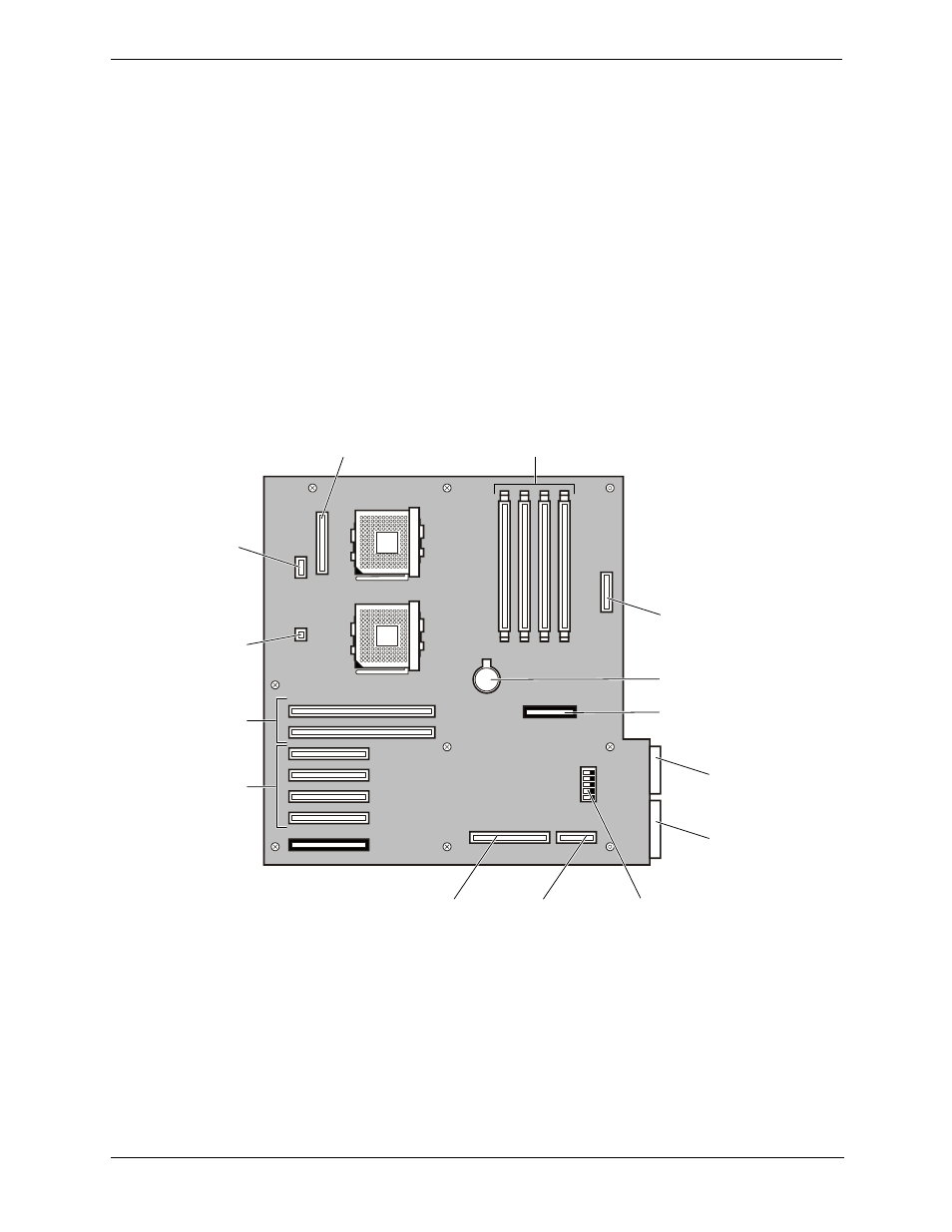
9. Disconnect all the cables from the System Board. The cable configuration may vary depending on what is
installed in the system. See .
Figure 7-11. System Board Connectors
10. Remove the power cable from the plastic holder on top of the chassis.
11. Remove the Control Panel cable and the IDE cable from the System Board chassis by pulling back on the
plastic tab, then pulling out on the center piece to open the latch.
12. Remove the processor(s) and DIMMs. See the instructions in previous chapters on how to remove the
processors and DIMMs. Place them in appropriate anti-static bags or on an anti-static pad.
6
5
4
3
0
1
2
3
2
1
1
2
3
4
5
Main Power
Cable
Two 64 bit
PCI Slots
Four 32 bit
PCI Slots
DIMM
(4 places)
DIP
Switch
SCSI B
Connector
Misc. Signal
Cable, To Power
Distribution Board
Battery
SCSI A
Connector
IDE Cable
To CD Drive
To Floppy
Drive
To Control
Panel
Rear Locator
Connector
Intrusion
Switch
Connector