Eaton Compressor & Fabrication C-STOV-MC001-E1 User Manual
Page 8
8
EATON Char-Lynn Steering Catalog C-STOV-MC001-E1 July 2006
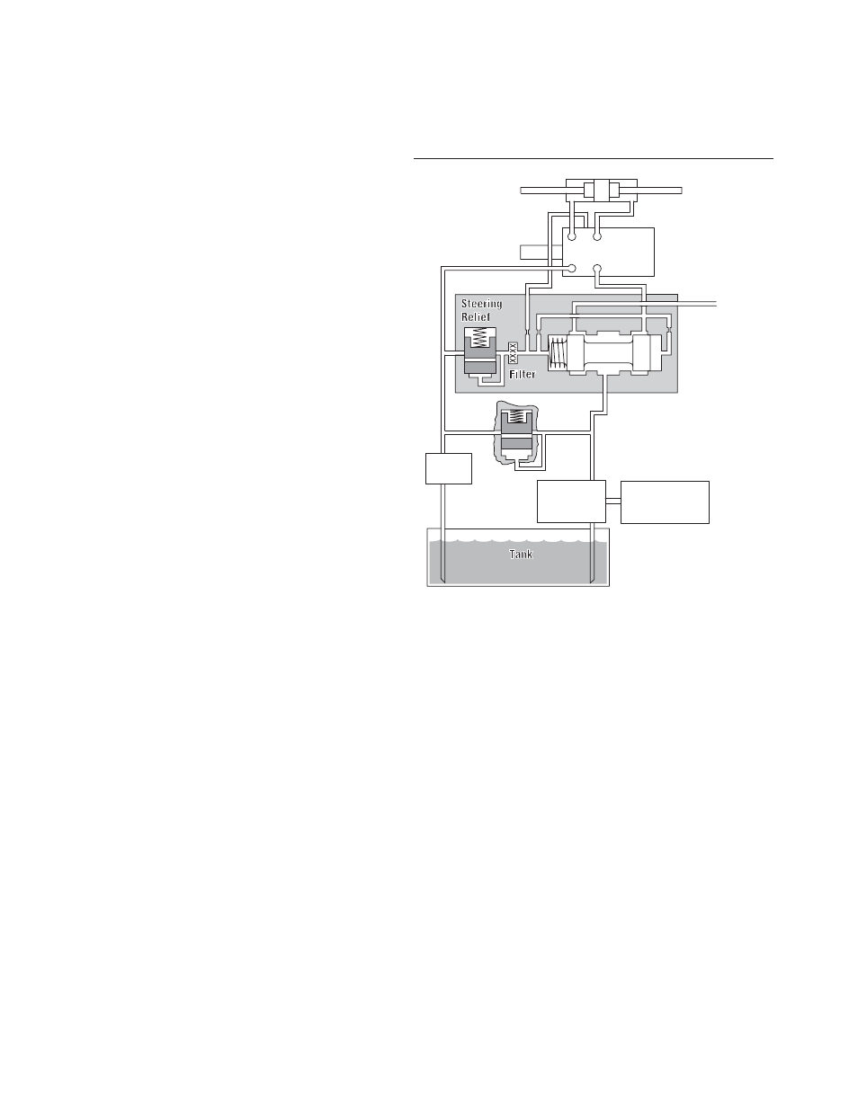
Hydraulic Circuit
Explanation
Neutral Circuits:
Load Sensing
Load Sensing Circuits
Char-Lynn load sensing
power steering uses
conventional or load sensing
power supplies to achieve
load sensing steering. The
use of a load sensing
steering unit and a priority
valve in a normal power
steering circuit offers the
following advantages:
• Provides smooth
pressure compensated
steering because load
variations in the
steering circuit do not
affect axle response or
maximum steering rate.
• Provides true power
beyond system
capability by splitting
the system into two
independent circuits.
Pressure transients are
isolated in each circuit.
Only the flow required
by the steering
maneuver goes to the
steering circuit. Flow
not required for
steering is available for
use in the auxiliary
circuits.
• Provides reliable operation
because the steering
circuit always has flow
and pressure priority.
Char-Lynn load sensing
steering control units and
priority valves can be used with
open center, closed center or
load sensing systems. Use in
an open center system with a
fixed displacement pump or a
closed center system with a
pressure compensated pump,
offers many of the features of a
load sensing system. Excess
flow is available for auxiliary
circuits.
Listed below are the
components of a typical load
sensing control circuit and a
brief application description.
Pump—May be fixed
displacement, pressure
compensated,
or flow and pressure
compensated design.
Priority Valve—Sized for
design pressure drop at
maximum pump output flow
rate and priority flow
requirements. The minimum
control pressure must assure
adequate steering flow rate
and must be matched with
the steering control unit.
A dynamic signal priority
valve must be used with a
dynamic signal steering
control unit.
Steering Control Unit—
Designed for specific rated
flows and control pressures.
It must be matched with a
control pressure in the
priority valve to obtain
maximum steering rates.
Higher flow rates require
higher control pressures.
Neutral internal bleed
assures component
temperature equalization.
LS Line—A LS line is always
needed to sense pressure
downstream from the
variable control orifice in the
steering control unit. This is
balanced by an internal
passage to the opposite side
of the priority control spool.
The total system
performance depends on
careful consideration of the
control pressure chosen and
pressure drop in the CF line.
Steering Relief Valve—
Must be factory set at least
10 bar [145 PSl] above the
maximum steering cylinder
pressure requirement. Most
of the flow will be directed
to the auxiliary circuit (EF)
when the relief setting is
exceeded.
System Main Relief
Valve—A pressure relief
valve for the auxiliary circuit
and/or a main safety valve for
the protection of the pump is
recommended and sized for
the maximum pump output
flow rate. If a main relief valve
is used, it must be set above
the priority circuit steering
relief valve pressure setting.
Filter
Pump
Prime Mover
Main
Relief
Manual
Input
Steering Cylinder
Load Sensing
Steering Unit
T
LS
T
P
L
R
Priority Valve
High Pressure
Carryover
P
CF
EF
DS
LS
PP
Dynamic Signal
LS — Load Sensing
DS— Dynamic Signal
PP — Pilot Pressure
CF — Control Flow
EF — Excess Flow