ProSoft Technology PLX81-EIP-61850 User Manual
Page 35
PLX8x-EIP-61850 ♦ Communication Gateway
Configuring the PLX8x-EIP-61850 Gateway
Server to
IEC 61850 Client
User Manual
ProSoft Technology, Inc.
Page 35 of 167
July 2, 2015
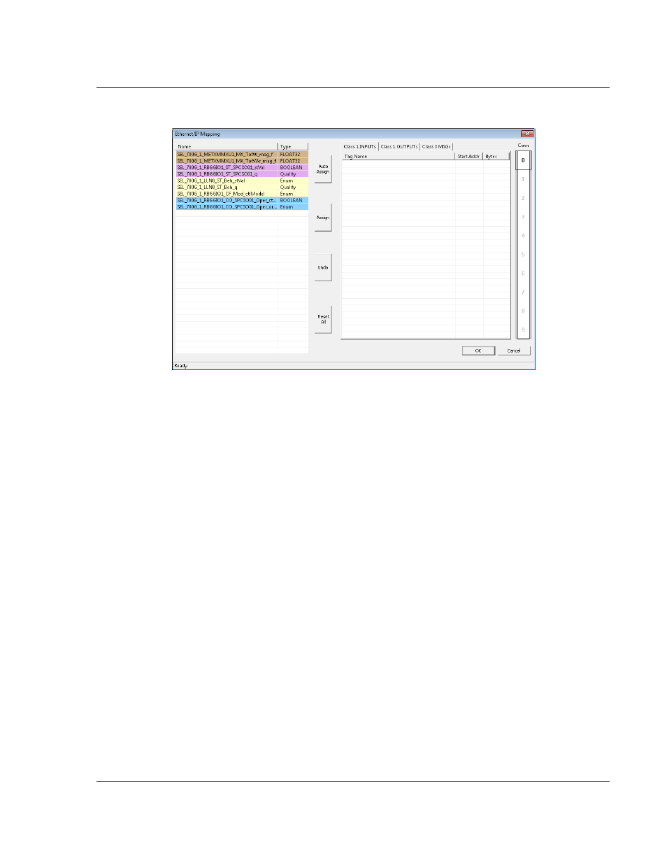
This displays the EtherNet/IP Mapping Tool window.
The mapped tags (Data Attributes) appear on the left-hand side of the window.
The tags are highlighted in one of three colors:
Tags that can be read from the IED are highlighted in yellow.
Tags that can be written to the IED are highlighted in blue.
Tags that are string data are highlighted in Brown. This includes tags from
Reports.
Tags that come from GOOSE messages are highlighted in purple.
You must map tags to an output on the right-hand side. You must map the
available tags on the left-hand side to one of the three tabs on the right-hand side
of the window.
Class 1 INPUTS is for tags that can be read from the IED (yellow, brown,
purple to Firefox). These are output on the gateway EtherNet/IP as Class 1
messages. For more on Class 1 inputs, see Specifications - EtherNet/IP on
page 80.
Class 2 OUTPUTS is for tags that can be written to the IED (blue). Write tags
are highlighted in blue. These can be written by the PLC to EtherNet/IP on
the gateway as Class 1 messages.
Class 3 MSGs is for any tag. In particular, if your application requires more
Data Attributes than the supported number of bytes that can be transferred by
EtherNet/IP Class 1 messaging, you must use Class 3 messages. These
must be explicitly read or written by the PLC using Class 3 messaging. For
more on Class 3 messages, see Specifications - EtherNet/IP on page 80.