2 preparing the installation site, Preparing the installation site – KACO Powador XP200-HV TL User Manual
Page 16
Mounting the inverter
Page 16
Operating Instructions Powador XP200-HV TL, XP250-HV TL, XP350-HV TL_EN
Electrician
6.2
Preparing the installation site
NOTE
The serial numbers of the left and the right inverter cabinet must be identical (see inside of the left
cabinet doors).
Do not connect two inverter cabinets with different serial numbers.
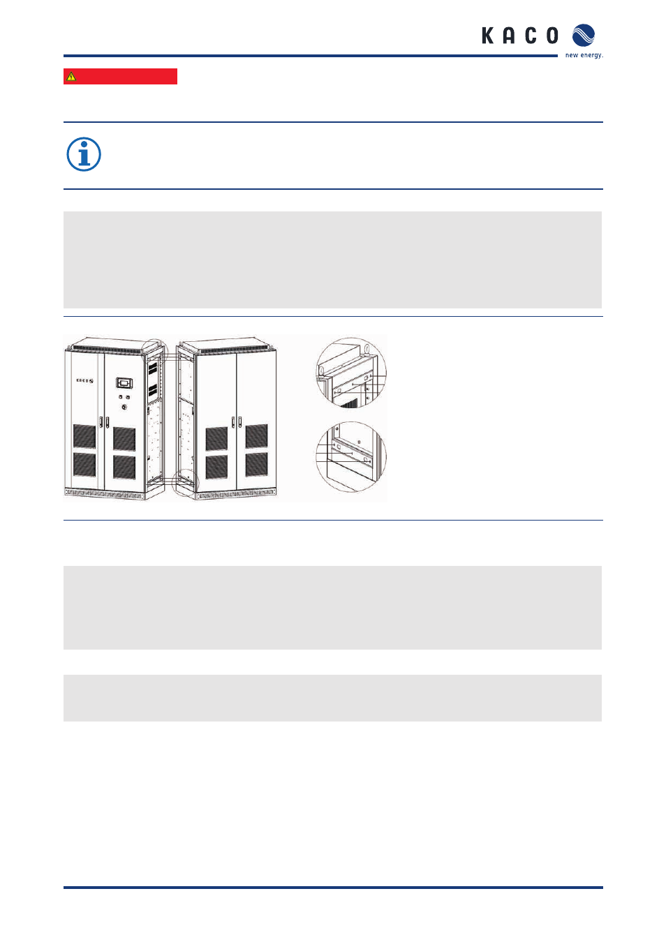
Setup of the inverter
Each inverter cabinet is equipped with 6 bore holes on the mounting side (Figure 8). The corresponding screws,
nuts and washers are delivered in a plastic bag inside the left inverter cabinet.
↺ The serial numbers of the left and the right inverter cabinet are identical.
1. Connect the two inverter cabinets through the 6 bore holes with the supplied screws, nuts and washers.
2. Tighten the screws (tightening torque: 25 ... 30 Nm).
Figure 8: Mechanical connection between left and right cabinets
Cable routing
"
Lay AC power cables, DC power cables and communication cables separately to avoid interferences.
"
Make the same grounding potential available for all communication cables.
"
Ensure proper grounding of all communication cables at the same potential.
"
If possible, allow communication cables to be routed close to ground potential.
Requirements for auxiliary supply
"
In case the inverter is used with an external power supply, dimension the external power supply properly.
The following values of power consumption serve as reference values.