4 trial operation, E-42, Screwdriver – Yaskawa Junma Series SERVOPACK User Manual
Page 43
E-42
4 Trial Operation
Failures caused by incorrect wiring or wrong voltage application in the brake circuit may damage
the equipment or cause an accident resulting in death or injury.
Follow the procedures and instructions for wiring and trial operation precisely as described in this
manual.
Use the following procedure to perform trial operation.
Step
Details
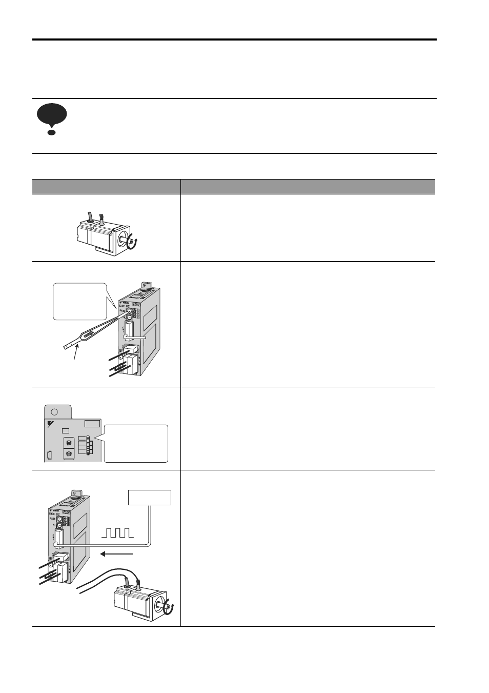
1. Installation
• Install the SERVOPACK and servomotor under the installation condi-
tions.
Do not connect the servomotor shaft to the machine.
2. Wiring and PULSE Settings
• Wire the power supply connector, servomotor main circuit cable,
encoder cable, and the I/O signal cable correctly following the pro-
cedures in 3 Wiring.
• If a servomotor with a brake is used, connect all signal cables
including those for the brake power supply and the relay.
• Use the PULSE rotary switch to select the type of controller’s out-
put pulse and set the resolution of the servomotor.
Note: Use the screwdriver to change the setting
on the rotary switch. Never use the
screwdriver for any purpose other than
setting the rotary switch.
3. LED Check
• Turn ON the power and confirm that the REF indicator is lit orange
or green. If the indicator is orange, turn ON the servo ON (S-ON)
input signal and check that the color of the REF indicator changes
from orange to green.
• If the REF indicator is not orange or green, or the indicator of the
AL1, AL2 or AL3 alarm is red, refer to 6 Troubleshooting and clear
the alarm.
4. PULSE Reference Input 1
• Input the reference pulse from the controller, and then check on
the number of the pulses and servomotor’s rotational direction.
Make sure the servomotor rotates in the correct direction while the
REF indicator is blinking green.
• If the servomotor does not rotate according to the reference, refer
to 6 Troubleshooting and clear the alarm.
NOTE
Select the
PULSE setting
with the rotary
switch.
Screwdriver
APA-OY
200V
YASKAWA
SJDE- 04 APA-OY
FIL
PULSE
REF
AL1
AL2
AL3
C
0
8
9
A
B DE
F
45
3
2
6
7
1
C
0
8
9
A
B DE
F
45
3
2
6
7
1
Check that the
color of the REF
indicator changes
to orange or green.
Controller
Reference pulse
APA-OY