12 connection examples of input signal, Line driver output, Open-collector output – Yaskawa Junma Series SERVOPACK User Manual
Page 38: 12 conne, English, 12 connection examples of input signal e-37
3.12 Connection Examples of Input Signal
E-37
English
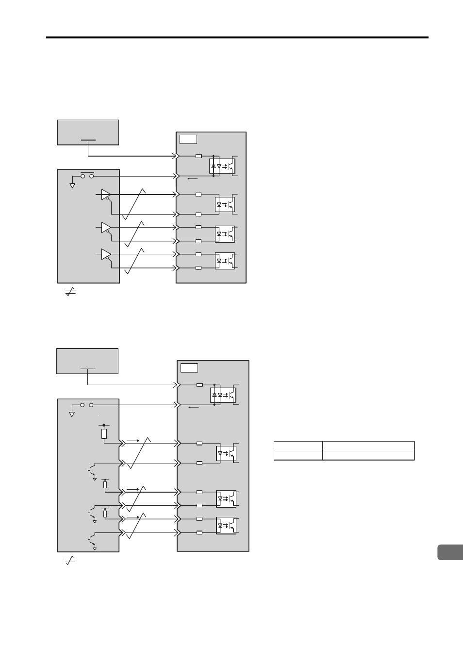
3.12 Connection Examples of Input Signal
Line Driver Output
Applicable line driver: SN75174 or MC3487 (Manufactured by Texas Instruments or equivalent)
Open-collector Output
Set the current limit resistors R1 through R3 so that the input current (i) will be within the following range.
Input Current (i) = 7 mA to 15 mA
SERVOPACK
Photocoupler
Host Controller
1
2
9
8
4
3
/PULS
SIGN
/SIGN
CLR
/CLR
PULS
75
Ω
7mA
∗
∗ޓޓ Twisted-pair wires
CN1
75
Ω
75
Ω
75
Ω
75
Ω
75
Ω
5
6
3.4k
Ω
/S-ON
+24VIN
0V
24VDC Power Supply
+24V
Photocoupler
1
2
9
8
4
3
/PULS
SIGN
/SIGN
CLR
/CLR
PULS
∗
Vcc
R1
i
R2
Tr1
Tr2
Tr3
R3
i
i
75
Ω
75
Ω
75
Ω
75
Ω
75
Ω
75
Ω
SERVOPACK
Photocoupler
7mA
CN1
5
6
3.4k
Ω
/S-ON
+24VIN
0V
+24V
Examples:
When Vcc is +12V: R1 through R3=1 k
Ω
When Vcc is +24V: R1 through R3=2.2 k
Ω
When Vcc is +5V: R1 through R3=180
Ω
Note: The following signal logic applies for an
open-collector output.
Tr1 to Tr3 ON
Equivalent to high level input.
Equivalent to low level input.
Tr1 to Tr3 OFF
Host Controller
24VDC Power Supply
∗ޓޓ Twisted-pair wires