English – Yaskawa Junma Series SERVOPACK User Manual
Page 26
3.3 Standard Connection
E-25
English
Configure the holding brake circuit that is to be activated upon occurrence of emergency stop.
Note: 1. AVR1: 24 VDC power supply for brake
AVR2: 24 VDC power supply for
sequence
SW1: Power OFF switch
SW2: Power ON switch
MC1: Magnetic contactor
Ry1:
Brake relay
• Parts example
Surge absorber Okaya Electric Industries Co., Ltd. CRE-50500
(Sold as: Spark Quencher)
Flywheel diode Toshiba Corporation 1NH42
Brake relay
OMRON Corporation MY series
Varistor
Nippon Chemi-Con Corporation TNR7V121K
2. The ground protection circuit is designed for ground fault inside the motor windings
while the motor is running. Therefore, it may not protect the system under the following
conditions.
• A low-resistance ground fault occurs between the main circuit cable and connector for the servomotor.
• The power supply is turned ON during a ground fault.
To configure a safer system, install an earth leakage breaker for protection against over-
loads and short-circuiting, or install an earth leakage breaker combined with a wiring cir-
cuit breaker for ground protection.
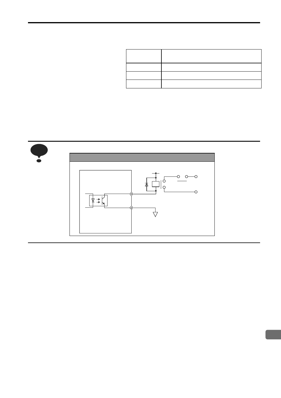
Relay Circuit Example
NOTE
SERVOPACK
0 V
Emergency Stop
5 VDC to 24 VDC