10 wiring the encoder connector (cn2), Connection diagram for standard encoder cable, 10 w – Yaskawa Junma Series SERVOPACK User Manual
Page 36: English
3.10 Wiring the Encoder Connector (CN2)
E-35
English
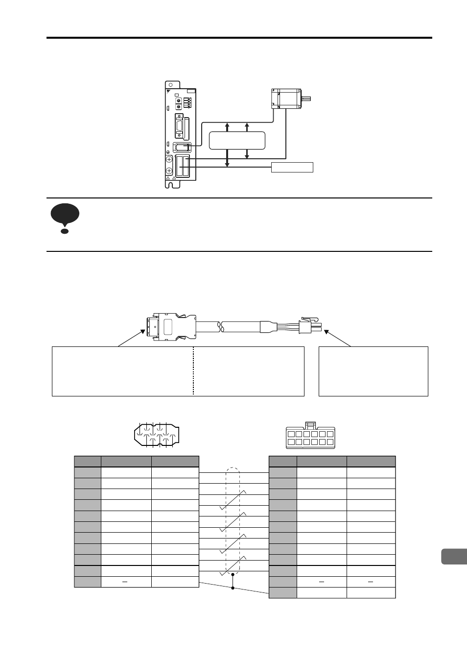
3.10 Wiring the Encoder Connector (CN2)
• Separate the encoder cable at least 300 mm from power lines (i.e., high-voltage lines such as the
power supply line and servomotor main circuit cable).
• Do not bundle with or run the encode cable in the same duct as power lines.
• Be sure that the maximum wiring length of the encoder cable is 20 m.
Connection Diagram for Standard Encoder Cable
If a user-prepared encoder cable is used for relaying, refer to the following connection diagram for the standard
cable (JZSP-CHP800- Cable with Connectors on Both Ends) and wire the encoder cable.
Note: Pin numbers are given on the connector as well.
Separate by
300 mm or more
Power Supply
200V
YASKAWA
SJDE- 04 APA-OY
FIL
PULSE
REF
AL1
AL2
AL3
L1
L2
+
CNA CNB
U
V
W
-
C
N
2
C
N
1
C
0
8
9
A
B DE
F
45
3
2
6
7
1
C
0
8
9
A
B DE
F
45
3
2
6
7
1
NOTE
Pin No.
Signal Name
1
2
3
4
5
6
7
8
9
10
Shell
PG5V
PG0V(GND)
Phase A (+)
Phase A (-)
Phase B (+)
Phase B (-)
Phase /Z
Phase U
Phase V
Phase W
Lead Color
Red
Black
Blue
Blue/White
Yellow
Yellow/White
Purple
Gray
Green
Orange
Shield
Red
Black
Blue
Blue/White
Yellow
Yellow/White
Purple
Gray
Green
Orange
Shield
Lead Color
Pin No.
Signal Name
1
2
3
4
5
6
7
8
9
10
11
12
PG5V
PG0V(GND)
Phase A (+)
Phase A (-)
Phase B (+)
Phase B (-)
Phase /Z
Phase U
Phase V
Phase W
Shield
SERVOPACK Connector
(Viewed from soldered side)
Servomotor Connector
(Viewed from cable insertion side)
Shield wire
6 5 4 3 2 1
12 11 10
8 7
9
9 7 5 3 1
2
4
6
8
10
SERVOPACK end
y
Crimp type (Gray)
Plug and Cable Cover Set: 54599-1005
Plug Housing: 51209-1001
Crimp Terminals: 59351-8087(Chain) or
59351-8187 (Loose wires)
(Molex)
y
Solder type (Black)
Shell Kit: 36310-3200-008
Receptacle: 36210-0100FD (3M)
Motor end
Receptacle: 5557-12R-210
Terminals: 5556T2 (Chain) or
5556T2L(Loose wires)
(Molex)