Yaskawa VS-616PS5 Series Programming Manual User Manual
Page 67
VS-616PS5 Programming Manual
67
H2
Digital Outputs
The VS-616PS5 has three multi-function digital outputs for the indication of various
conditions, including speed detection, speed agree, zero speed, overtorque detec-
tion, and many others. This section includes descriptions of these functions.
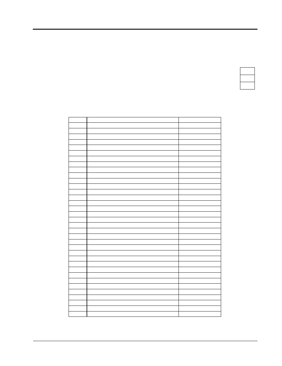
The following table lists the function selections for the multi-function digital outputs
(terminals 9, 25 & 26), and indicates the control modes during which each function
can be enabled.
H2-01 Multi-function Output 1 Selection (terminal 9, 10)
B
H2-02 Multi-function Output 2 Selection (terminal 25, 27)
B
H2-03 Multi-function Output 3 Selection (terminal 26, 27)
B
Setting
Function
Reference Page
0
During Run 1 (factory default, H2-01)
68
1
Zero-speed (factory default, H2-02)
68
2
Speed Agree 1 (factory default, H2-03)
68
3
Desired Speed Agree 1
68
4
Speed Detection 1
69
5
Speed Detection 2
69
6
Inverter Ready
69
7
DC Bus Undervoltage
69
8
Baseblock 1 - N.O.
69
9
Speed Reference Selection
69
A
Run Command Selection
69
B
Overtorque Detection 1 - N.O.
70
C
Loss of Speed Reference
70
D
Dynamic Braking Resistor (DB) Overheat
70
E
Fault
70
F
Not used
-
10
Alarm (Minor fault)
70
11
Fault Reset
70
12
Timer Output
70
13
Speed Agree 2
70
14
Desired Speed Agree 2
71
15
Speed Detection 3
71
16
Speed Detection 4
71
17
Overtorque Detection 1 - N.C.
72
18
Overtorque Detection 2 - N.O.
72
19
Overtorque Detection 2 - N.C.
72
1A
During Reverse Run
72
1B
Baseblock 2 - N.C.
72
1D
Monitoring/ Regenerating Mode
72
1E
Automatic Restart
72
1F
Overload (OL1) Pre-alarm
72
20
OH Pre-alarm
72
30
Current/torque Limit
73
31
Speed Limit
73
37
During Run 2
73
Section H: Control Circuit Terminal Parameters
H2 Digital Outputs