Signal – SMA CLUSTER CONTROLLER Installation User Manual
Page 64
4. On the connection cable, mark the terminal and the pin row to which the connection cable is
assigned. Use the supplied cable tie with caption field.
5. Write down the terminal assignment on the supplied supplementary sheet.
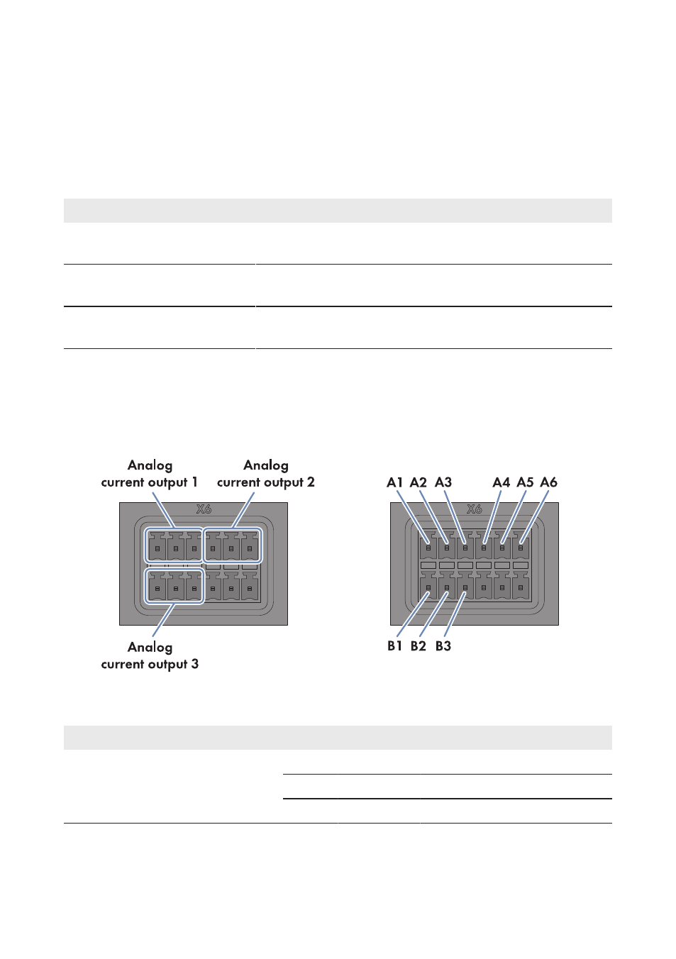
6.12.5.3 Connecting a Remote Terminal for Feedback via Analog Signal
You can have the following information fed back via the three analog current outputs:
Analog current output
Reported information
1
Value for active power limitation that the Cluster Controller is
currently sending to the inverters in the system
2
Value for the reactive power setpoint that the Cluster Controller
is currently sending to the inverters in the system
3
Current total active power of the system as a percentage of the
maximum nominal system power
Requirements:
☐ The remote terminal must be technically suitable for connection to the analog outputs (see
☐ The connection cable must be prepared for connection to the multipole plug (see Section 6.5,
Figure 27: Pin assignment for the pin groups Analog current output 1, Analog current output 2 and
Analog current output 3
Pin group
Pin
Signal
Explanation
Analog current output 1
Feedback for current active power lim-
itation
A1
I+
Current output
A2
I−
Current return
A3
GND
Shield ground
6 Connection and Commissioning
SMA Solar Technology AG / SMA America, LLC
Installation Manual
ClusterController-IA-en-14
64