Signal – SMA CLUSTER CONTROLLER Installation User Manual
Page 63
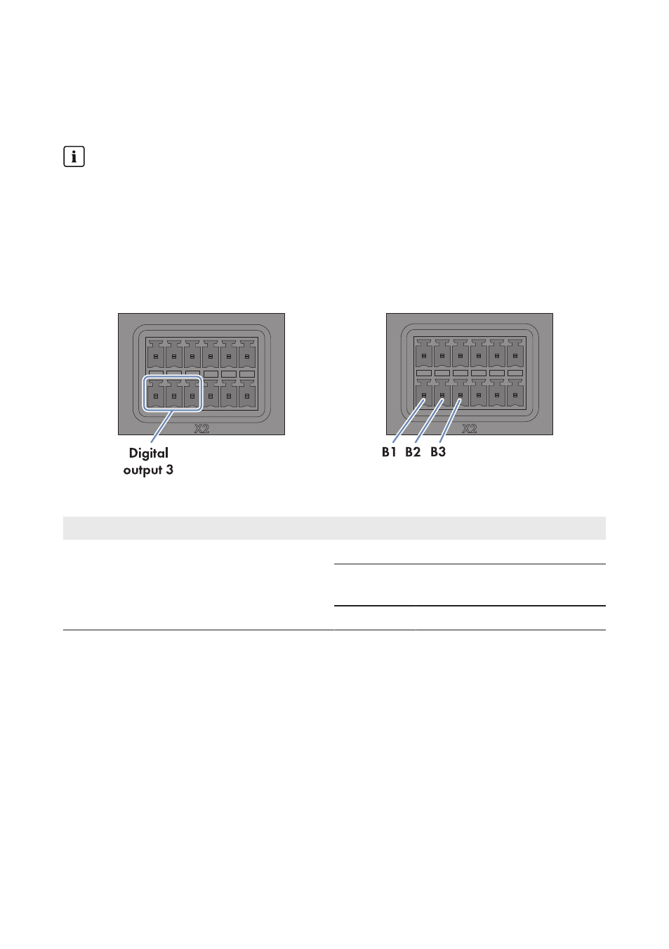
6.12.5.2 Connecting a Remote Terminal for Feedback via Digital Signal
Via the pin group Digital output 3, you can provide feedback on whether the Cluster Controller
has sent a grid operator setpoint for active power limitation to the inverters in the system.
Observe the maximum load capacity of the relay contacts
The relay contacts may be loaded with a maximum switching power of 30 W and a maximum
voltage of 48 V
DC
.
Requirements:
☐ The remote terminal must be technically suitable for connection to the digital output (see
☐ The connection cable must be prepared for connection to the multipole plug (see Section 6.5,
Figure 26: Pin assignment for pin group Digital output 3
Pin group
Relay
Pin
Signal
Explanation
Digital output 3
Response contact for current active
power limitation
C
B1
NC
Back contact
B2
CO
Change-over con-
tact
B3
NO
Front contact
Procedure:
1. Connect the connection cable to the remote terminal (see the manual from manufacturer). Trim
the unneeded insulated conductors up to the cable shield and note down the conductor colors.
2. Connect the connection cable to the six-pole plug:
• Depending on the remote terminal and the pin assignment of the pin group Digital
output 3, identify the conductor entries that are required for connecting the connection
cable.
• Release the required conductor entries using a screwdriver and insert the insulated
conductors into the conductor entries. Observe the pin assignment.
3. Insert the six-pole plug into pin row B in terminal X2.
6 Connection and Commissioning
SMA Solar Technology AG / SMA America, LLC
Installation Manual
63
ClusterController-IA-en-14