SMA CLUSTER CONTROLLER Installation User Manual
Page 55
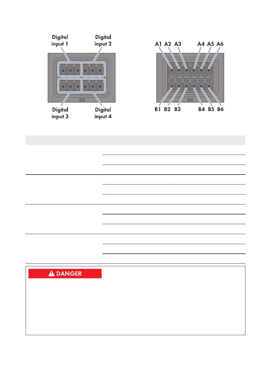
Figure 20: Pin assignment for pin groups on terminal X4
Pin group
Pin
Pin assignment
Explanation
Digital input 1
Signal 1 of 4 for active power
limitation
A1
24 V
Voltage supply output
A2
IN
Input
A3
GND
Reference potential
Digital input 2
Signal 2 of 4 for active power
limitation
A4
24 V
Voltage supply output
A5
IN
Input
A6
GND
Reference potential
Digital input 3
Signal 3 of 4 for active power
limitation
B1
24 V
Voltage supply output
B2
IN
Input
B3
GND
Reference potential
Digital input 4
Signal 4 of 4 for active power
limitation
B4
24 V
Voltage supply output
B5
IN
Input
B6
GND
Reference potential
Danger to life due to electric shock caused by incorrect connection of the ripple control
receiver
Incorrect connection of the ripple control receiver can result in grid voltage on the
Cluster Controller enclosure.
• Do not connect the insulated conductors of the connection cable to the line conductors of the
ripple control receiver.
• When connecting, ensure that no bridge is being used in the ripple control receiver.
6 Connection and Commissioning
SMA Solar Technology AG / SMA America, LLC
Installation Manual
55
ClusterController-IA-en-14