SMA CLUSTER CONTROLLER Installation User Manual
Page 37
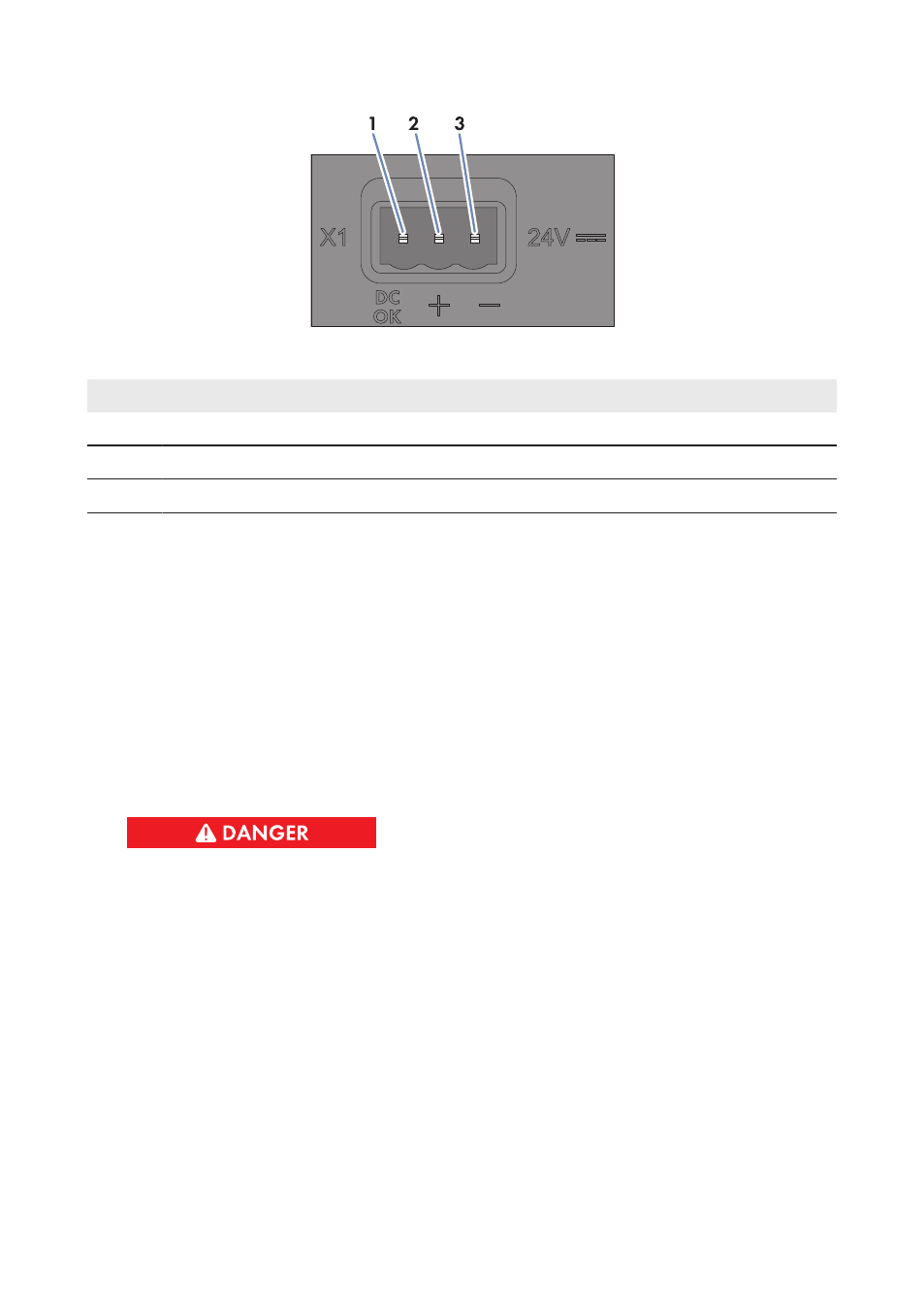
Figure 10: Pin assignment for terminal X1
Pin
Signal
Explanation
1
Not assigned
Reserved for future applications
2
24 V
Input voltage 24 V DC
3
GND
Ground
Procedure:
1. Mount the power supply unit (see the manual from manufacturer).
2. Connect the connection cable to the power supply unit (see manual from manufacturer). Trim
the unneeded insulated conductors up to the cable sheath and note down the conductor
colors.
3. Connect the connection cable to the three-pole plug. Unlock conductor entries 2 and 3 with a
screwdriver and insert the insulated conductors into the conductor entries. Observe the pin
assignment.
4. Connect the three-pole plug to terminal X1 on the Cluster Controller.
5. Connect the AC connection cable to the power supply unit (see the manual from
manufacturer).
6.
Danger to life due to electric shock
Lethal voltages are present at the connection point of the utility grid.
• Disconnect the connection point from voltage sources and ensure that the connection
point is voltage-free.
6 Connection and Commissioning
SMA Solar Technology AG / SMA America, LLC
Installation Manual
37
ClusterController-IA-en-14