2 digital setpoint signal, 1 connection options – SMA CLUSTER CONTROLLER Installation User Manual
Page 53
Type of setpoint signal
Explanation
Analog signals
The setpoints are transmitted to the Cluster Controller as
analog current signals. Current signals from 0 mA to
20 mA can be transmitted for the active power limitation
and the reactive power setpoint.
Setpoint signal via Modbus client
The setpoints are transmitted via a Modbus client to the
network port X13 or X14 on the Cluster Controller (for in-
formation on Modbus configuration, see the Cluster Con-
troller user manual).
Closed-loop control
For Cluster Controller systems with self-consumption, the operating mode Closed-loop control is
used. In this operating mode, you can limit the active power fed in by the system at the grid-
connection point to a fixed percentage value. In addition to the total system power, the
Cluster Controller needs the measured actual value of the active power fed in at the grid-connection
point.
6.12.2 Digital Setpoint Signal
6.12.2.1 Connection Options
You have two options for each pin group on terminal X4:
• Connection of a signal source with potential-free relay contact
or
• Connection of a 24 V signal source with digital output signals
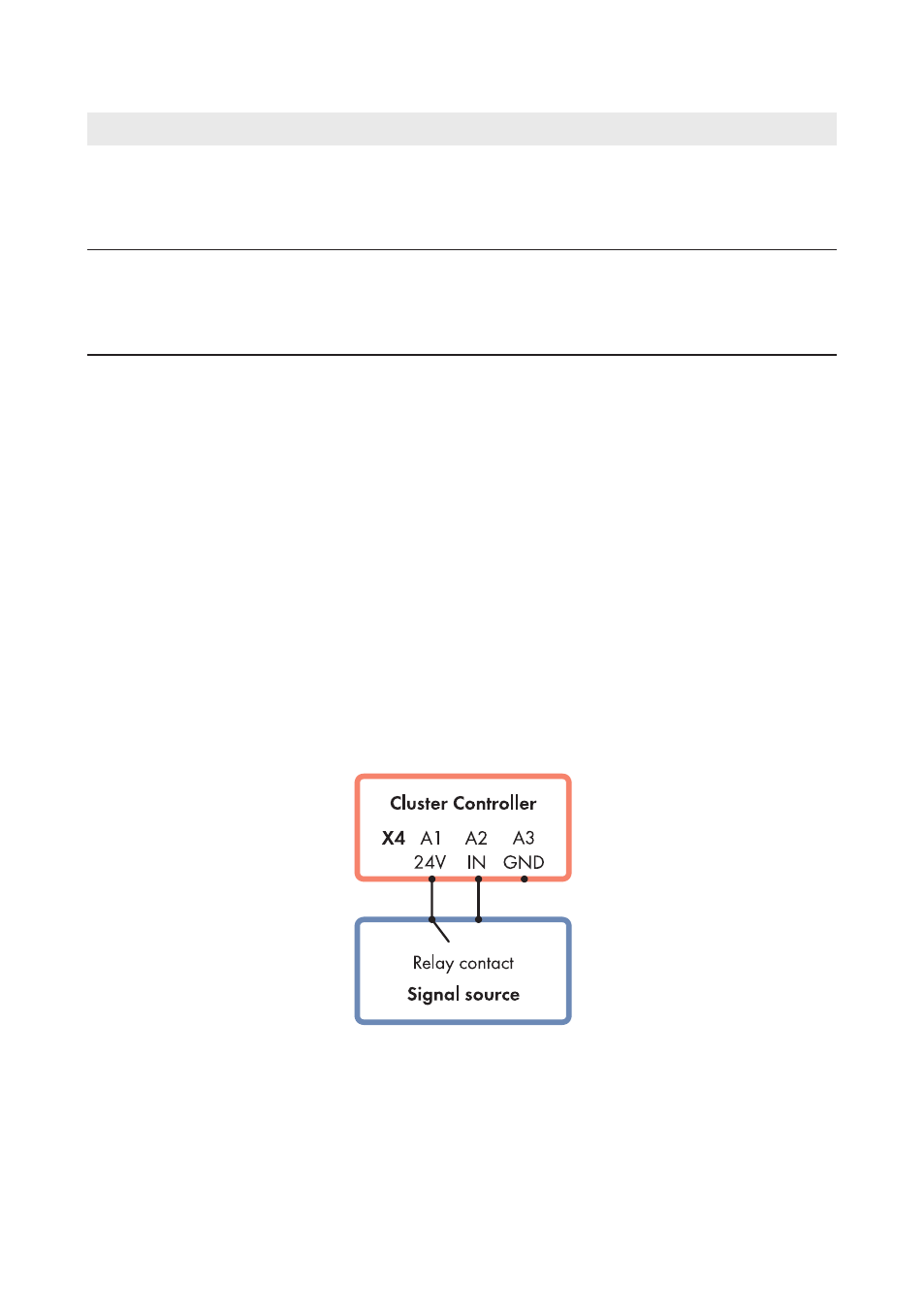
Connection of a signal source with potential-free relay contact
Figure 18: Connection of a signal source with potential-free relay contact (example)
6 Connection and Commissioning
SMA Solar Technology AG / SMA America, LLC
Installation Manual
53
ClusterController-IA-en-14