SMA CLUSTER CONTROLLER Installation User Manual
Page 45
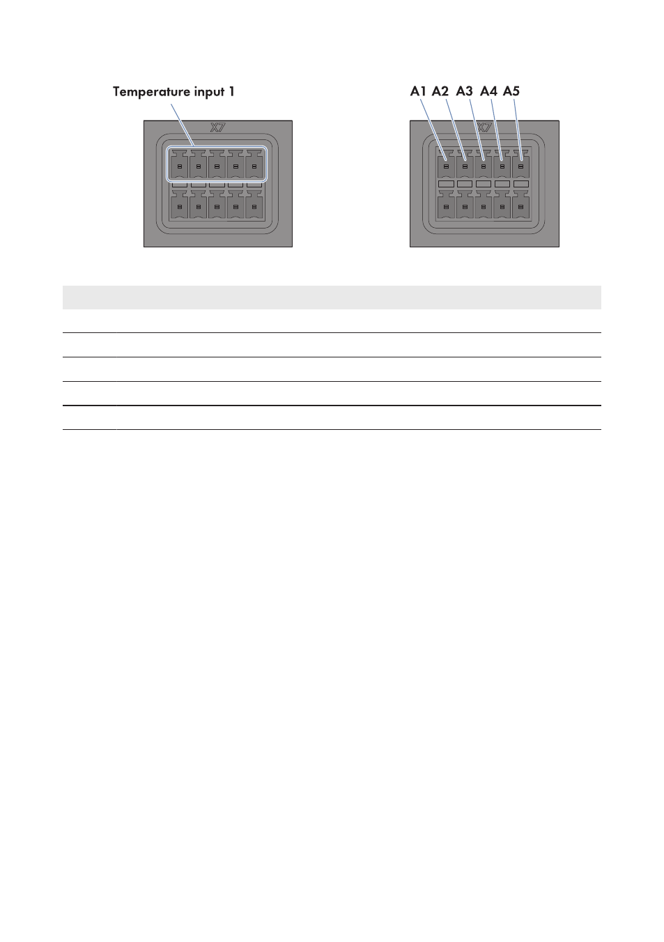
Figure 13: Pin assignment for pin group Temperature input 1
Pin
Signal
Explanation
A1
GND
Shield ground
A2
I+
Current input
A3
V+
Voltage input
A4
V−
Voltage return
A5
I−
Current return
Procedure:
1. Connect the connection cable to the outside temperature sensor (see the manual from
manufacturer). Trim the unneeded insulated conductors up to the cable shield and note down
the conductor colors.
2. For connection to the Cluster Controller using two-conductor connection technology, perform
the following steps:
• On the five-pole plug, unlock conductor entry 1 using a screwdriver and insert the
insulated conductor of the wire into the conductor entry.
• On the five-pole plug, unlock conductor entries 3 and 4 using a screwdriver and insert the
insulated conductors of the connection cable into the conductor entries. Observe the pin
assignment.
• At terminal X7 in pin row A, place a bridge between pin 2 and pin 3 and between pin 4
and pin 5.
3. For connection to the Cluster Controller using four-conductor connection technology, perform
the following steps:
• On the five-pole plug, unlock conductor entry 1 using a screwdriver and insert the
insulated conductor of the wire into the conductor entry.
• On the five-pole plug, unlock conductor entries 2, 3, 4 and 5 using a screwdriver and
insert the insulated conductors of the connection cable into the conductor entries.
Observe the pin assignment.
4. Insert the five-pole plug into pin row A in terminal X7.
6 Connection and Commissioning
SMA Solar Technology AG / SMA America, LLC
Installation Manual
45
ClusterController-IA-en-14