2 f undamentals of p a th f unctions – HEIDENHAIN iTNC 530 (340 49x-02) ISO programming User Manual
Page 196
196
6 Programming: Programming Contours
6.2 F
undamentals of P
a
th F
unctions
Entering more than three coordinates
The TNC can control up to 5 axes simultaneously. Machining with 5
axes, for example, moves 3 linear and 2 rotary axes simultaneously.
Such programs are too complex to program at the machine, however,
and are usually created with a CAD system.
Example:
Circles and circular arcs
The TNC moves two axes simultaneously in a circular path relative to
the workpiece. You can define a circular movement by entering a circle
center.
When you program a circle, the TNC assigns it to one of the main
planes. This plane is defined automatically when you set the spindle
axis during a tool call:
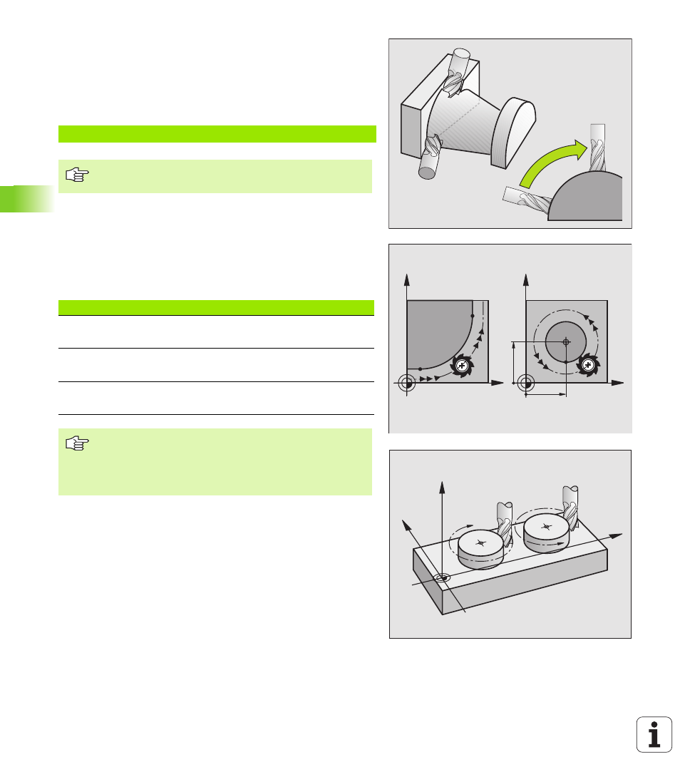
Direction of rotation for circular movements
If a circular path has no tangential transition to another contour
element, enter the direction of rotation with the following functions:
Clockwise direction of rotation: G02/G12
Counterclockwise direction of rotation: G03/G13
Radius compensation
The radius compensation must be in the block in which you move to
the first contour element. You cannot begin radius compensation in a
circle block. It must be activated beforehand in a straight-line block
(see “Path Contours—Cartesian Coordinates”, page 201).
Pre-positioning
Before running a part program, always pre-position the tool to prevent
the possibility of damaging it or the workpiece.
N123 G01 G40 X+20 Y+10 Z+2 A+15 C+6 F100 M3 *
The TNC graphics cannot simulate movements in more
than three axes.
Spindle axis
Main plane
Circle center
Z (G17)
XY, also
UV, XV, UY
I, J
Y (G18)
ZX, also
WU, ZU, WX
K, I
X (G19)
YZ, also
VW, YW, VZ
J, K
You can program circles that do not lie parallel to a main
plane by using the function for tilting the working plane
(see “WORKING PLANE (Cycle G80, software option1)”,
page 430) or Q parameters (see “Principle and
Overview”, page 484).
X
Y
X
Y
I
J
G02/G12
G03/G13
X
Z
Y