Configuring frame relay, Overview, Frame relay interface types – H3C Technologies H3C SR8800 User Manual
Page 60
52
Configuring frame relay
Overview
Frame relay is essentially simplified X.25 WAN technology. It uses statistical multiplexing technology and
can establish multiple virtual circuits over a single physical cable to make full use of network bandwidth.
Frame relay uses data link connection identifiers (DLCIs) to identify virtual circuits and maintain the status
of each virtual circuit with the Local Management Interface (LMI) protocol.
Frame relay interface types
As shown in
, frame relay enables communication between user devices such as routers and
hosts. The user devices are also called “data terminal equipment (DTE)”. They are connected to a frame
relay network through the DTE interface. The devices that provide access to the frame relay network for
DTEs are called “data communications equipment (DCE)”. A DCE is connected to a DTE with a DCE
interface on the user network interface (UNI) side and to a frame relay switch in the frame relay network
with a network-to-network interface (NNI) on the NNI side. The switches in the frame relay cloud are
interconnected with the NNI.
In actual applications, a DTE interface can connect to only a DCE interface, and an NNI interface can
connect to only an NNI interface. On a frame relay switch, the frame relay interface should be an NNI
or DCE interface.
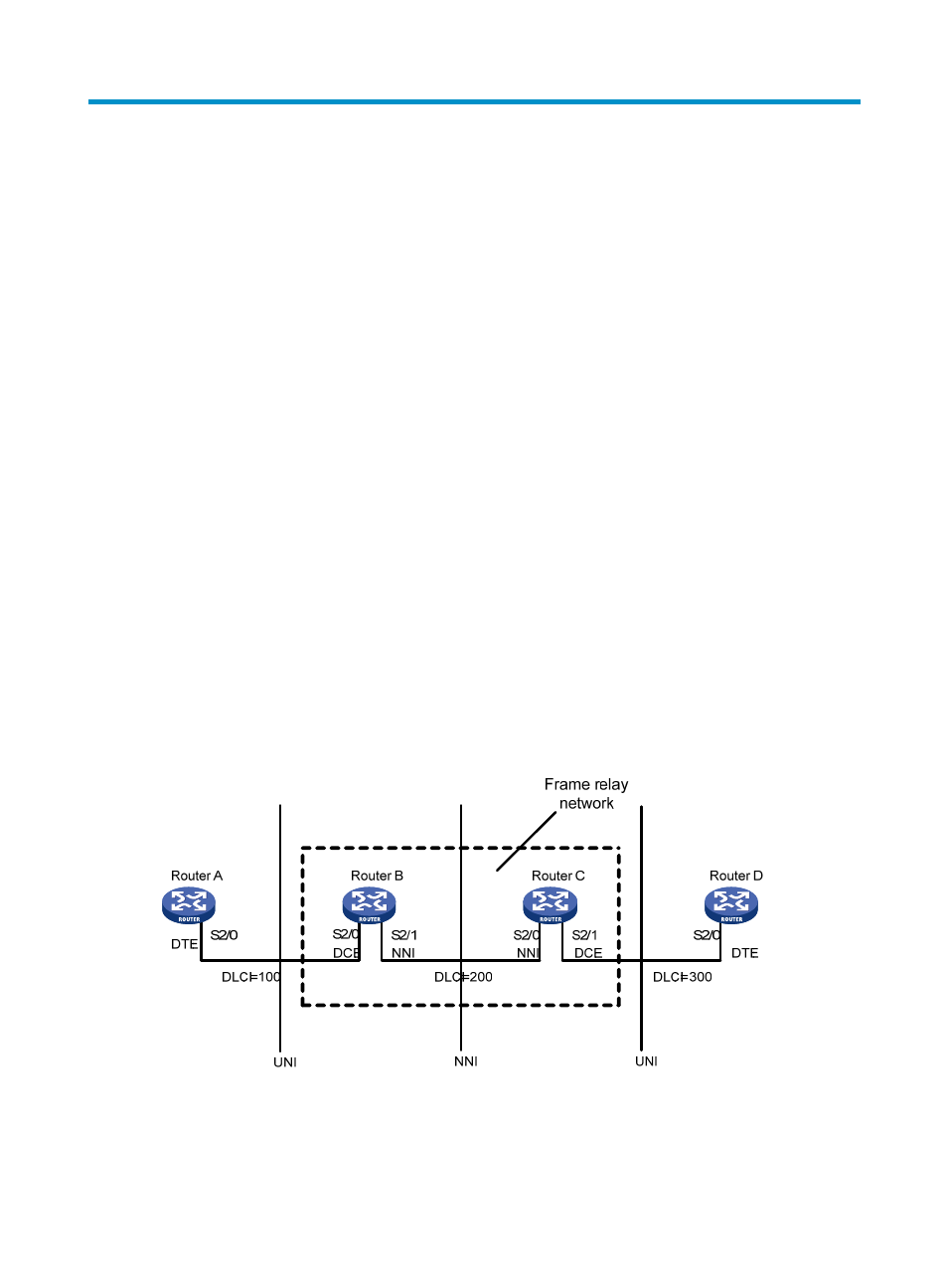
As shown in
, Router B and Router C form a simple frame relay network, to which DTE devices
Router A and Router D are attached. You can see that the DTE and DCE are identified on only the UNI
interface; a virtual circuit between two DTE devices can be assigned different DLCIs on different
segments.
Figure 14 An example frame relay network
- H3C SR6600-X H3C SR6600 H3C MSR 5600 H3C MSR 50 H3C MSR 3600 H3C MSR 30 H3C MSR 2600 H3C MSR 20-2X[40] H3C MSR 20-1X H3C MSR 930 H3C MSR 900 H3C WX6000 Series Access Controllers H3C WX5000 Series Access Controllers H3C WX3000 Series Unified Switches H3C LSWM1WCM10 Access Controller Module H3C LSWM1WCM20 Access Controller Module H3C LSQM1WCMB0 Access Controller Module H3C LSRM1WCM2A1 Access Controller Module H3C LSBM1WCM2A0 Access Controller Module