Configuration procedure – H3C Technologies H3C SR8800 User Manual
Page 23
15
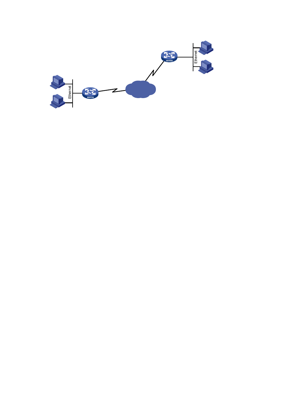
Figure 6 Network diagram
Configuration procedure
1.
Configure Router A:
# Create Layer 2 VE interfaces and assign them to the specified VLAN.
[RouterA] vlan 100
[RouterA-vlan100] quit
[RouterA] interface VE-Bridge 3/0/1
[RouterA-VE-Bridge3/0/1] port access vlan 100
[RouterA-VE-Bridge3/0/1] quit
# Create the PVCs to Router B and Router C and map them to the VE-bridge interfaces.
[RouterA] interface Atm 3/1/1
[RouterA-Atm3/1/1] pvc to_b 0/40
[RouterA-atm-pvc-Atm3/1/1-0/40-to_b] map bridge VE-Bridge 3/0/1
[RouterA-atm-pvc-Atm3/1/1-0/40-to_b] quit
2.
Configure Router B:
# Create Layer 2 VE interfaces and assign them to the specified VLAN.
[RouterB] vlan 100
[RouterB-vlan100] quit
[RouterB] interface VE-Bridge 3/0/1
[RouterB-VE-Bridge3/0/1] port access vlan 100
[RouterB-VE-Bridge3/0/1] quit
# Create the PVCs to Router A and Router C and map them to the VE-bridge interfaces.
[RouterB] interface Atm 3/1/1
[RouterB-Atm3/1/1] pvc to_a 0/50
[RouterB-atm-pvc-Atm3/1/1-0/50-to_a] map bridge VE-Bridge 3/0/1
[RouterB-atm-pvc-Atm3/1/1-0/50-to_a] quit
Host C
Host D
Host A
Host B
ATM network
Router A
Router B
ATM3/1 /1
ATM3/1/1
ve-bridge 3/0/1
VPI/VCI:0/40
VLAN 100
ve-bridge 3/0/1
VPI/VCI:0/50
VLAN 100
- H3C SR6600-X H3C SR6600 H3C MSR 5600 H3C MSR 50 H3C MSR 3600 H3C MSR 30 H3C MSR 2600 H3C MSR 20-2X[40] H3C MSR 20-1X H3C MSR 930 H3C MSR 900 H3C WX6000 Series Access Controllers H3C WX5000 Series Access Controllers H3C WX3000 Series Unified Switches H3C LSWM1WCM10 Access Controller Module H3C LSWM1WCM20 Access Controller Module H3C LSQM1WCMB0 Access Controller Module H3C LSRM1WCM2A1 Access Controller Module H3C LSBM1WCM2A0 Access Controller Module