Rip frr configuration example, Network requirements, Configuration procedure – H3C Technologies H3C S5560 Series Switches User Manual
Page 76
60
BkLabel: NULL BkNextHop: N/A
Tunnel ID: Invalid Interface: vlan-interface 300
BkTunnel ID: Invalid BkInterface: N/A
RIP FRR configuration example
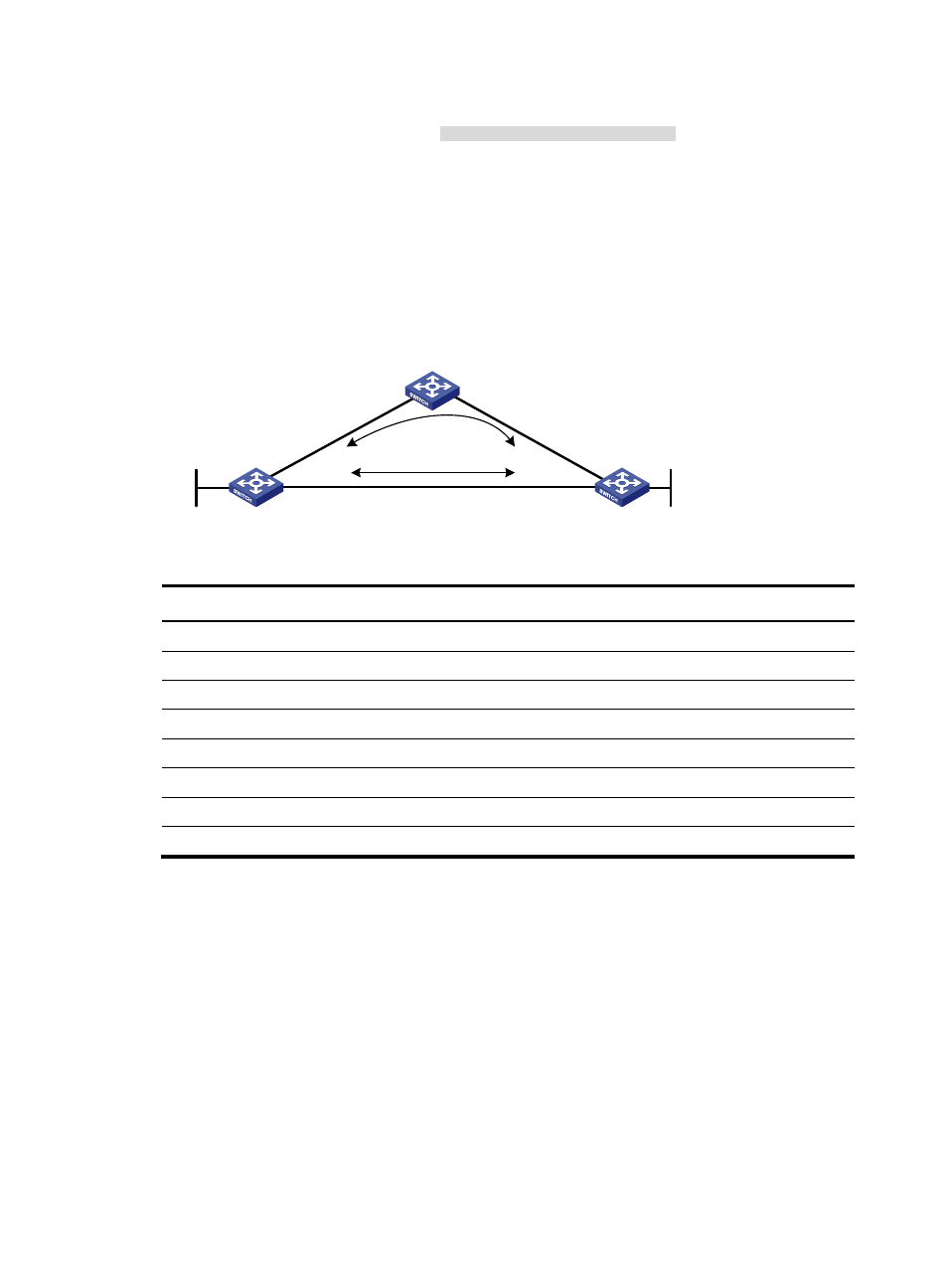
Network requirements
As shown in
, Switch A, Switch B, and Switch C run RIPv2. Configure RIP FRR so that when Link
A becomes unidirectional, services can be switched to Link B immediately.
Figure 14 Network diagram
Table 8 Interface and IP address assignment
Device Interface IP
address
Switch A
VLAN-interface 100
12.12.12.1/24
Switch A
VLAN-interface 200
13.13.13.1/24
Switch A
Loopback 0
1.1.1.1/32
Switch B
VLAN-interface 101
24.24.24.4/24
Switch B
VLAN-interface 202
13.13.13.2/24
Switch B
Loopback 0
4.4.4.4/32
Switch C
VLAN-interface 100
12.12.12.2/24
Switch C
VLAN-interface 101
24.24.24.2/24
Configuration procedure
1.
Configure IP addresses and subnet masks for interfaces on the switches. (Details not shown.)
2.
Configure RIPv2 on the switches to make sure Switch A, Switch B, and Switch C can communicate
with each other at Layer 3. (Details not shown.)
3.
Configure RIP FRR:
# Configure Switch A.
[SwitchA] bfd echo-source-ip 2.2.2.2
[SwitchA] ip prefix-list abc index 10 permit 4.4.4.4 32
[SwitchA] route-policy frr permit node 10
[SwitchA-route-policy-frr-10] if-match ip address prefix-list abc
[SwitchA-route-policy-frr-10] apply fast-reroute backup-interface vlan-interface
100 backup-nexthop 12.12.12.2
Switch A
Switch B
Switch C
Loop0
Vla
n-i
nt1
00
Vlan-int200
Vlan-int200
Vla
n-i
nt1
00
Vla
n-in
t10
1
Vla
n-in
t10
1
Loop0
Link A
Link B