Ipv6 bgp frr configuration example, Network requirements, Configuration procedure – H3C Technologies H3C S5560 Series Switches User Manual
Page 333
317
# Break down the path Switch C<—>Switch B<—>Switch A and then display route 1200::0/64 on
Switch C.
Summary Count : 1
Destination: 1200::/64
Protocol: BGP4+ Process ID: 0
SubProtID: 0x1 Age: 00h00m57s
Cost: 100 Preference: 255
Tag: 0 State: Active Adv
OrigTblID: 0x1 OrigVrf: default-vrf
TableID: 0xa OrigAs: 0
NBRID: 0x25000000 LastAs: 0
AttrID: 0x0 Neighbor: 2000::1
Flags: 0x10060 OrigNextHop: 2000::1
Label: NULL RealNextHop: FE80::20C:29FF:FE40:715
BkLabel: NULL BkNextHop: N/A
Tunnel ID: Invalid Interface: Vlan-interface201
BkTunnel ID: Invalid BkInterface: N/A
The output shows that Switch C communicates with network 1200::0/64 through the path Switch
C<—>Switch D<—>Switch A.
IPv6 BGP FRR configuration example
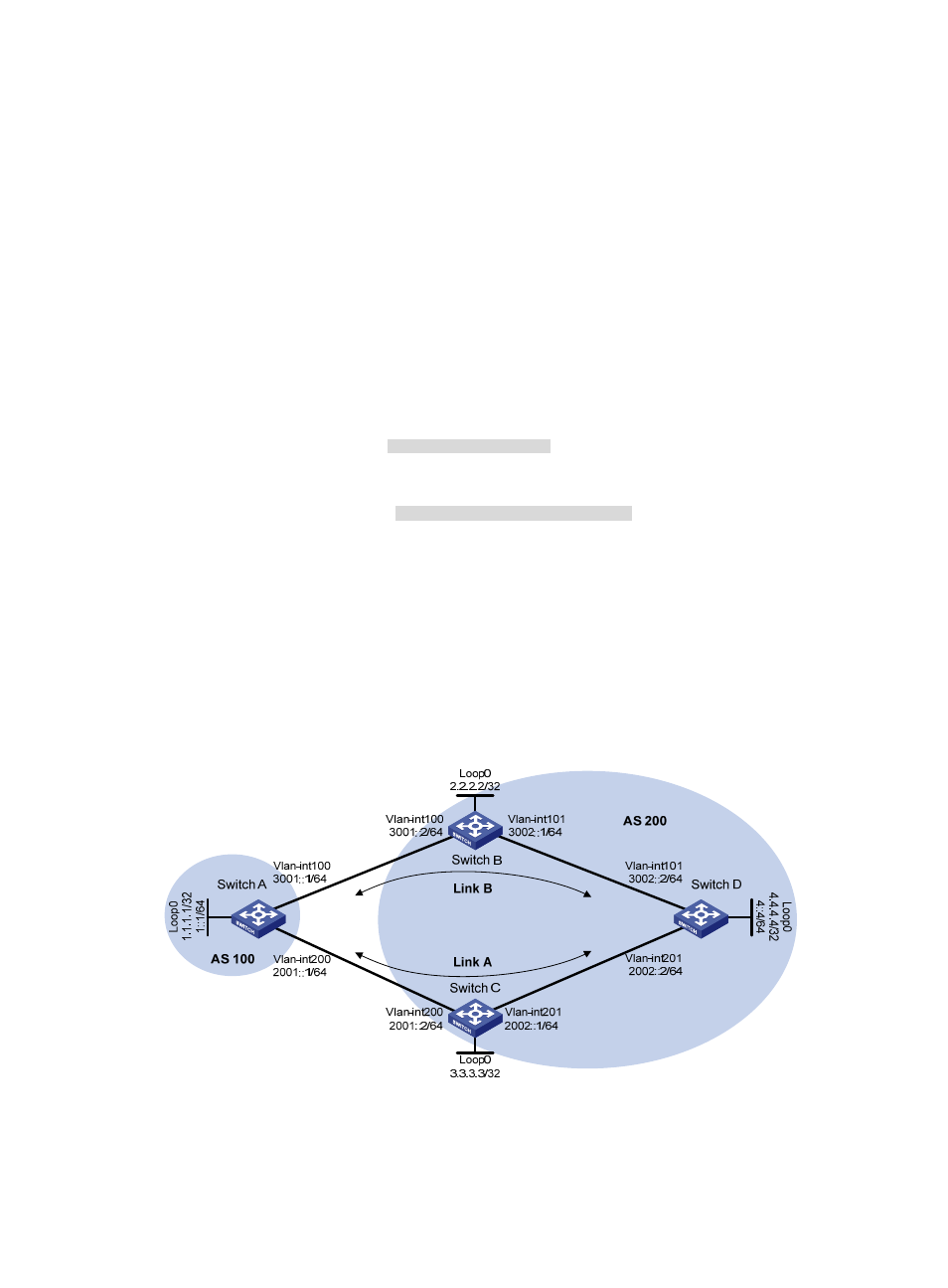
Network requirements
As shown in
, configuring BGP FRR so that when Link B fails, BGP uses Link A to forward traffic.
Figure 78 Network diagram
Configuration procedure
1.
Configure IPv6 addresses for interfaces. (Details not shown.)