Verifying the configuration, Ospfv3 nsr configuration example, Network requirements – H3C Technologies H3C S5560 Series Switches User Manual
Page 420: Configuration procedure
404
[SwitchC-ospfv3-1] router-id 3.3.3.3
[SwitchC-ospfv3-1] quit
[SwitchC] interface vlan-interface 100
[SwitchC-Vlan-interface100] ospfv3 1 area 1
[SwitchC-Vlan-interface100] quit
Verifying the configuration
# Perform a master/backup switchover on Switch A to trigger an OSPFv3 GR operation. (Details not
shown.)
# Restart OSPFv3 on Switch A to trigger an OSPFv3 GR operation. (Details not shown.)
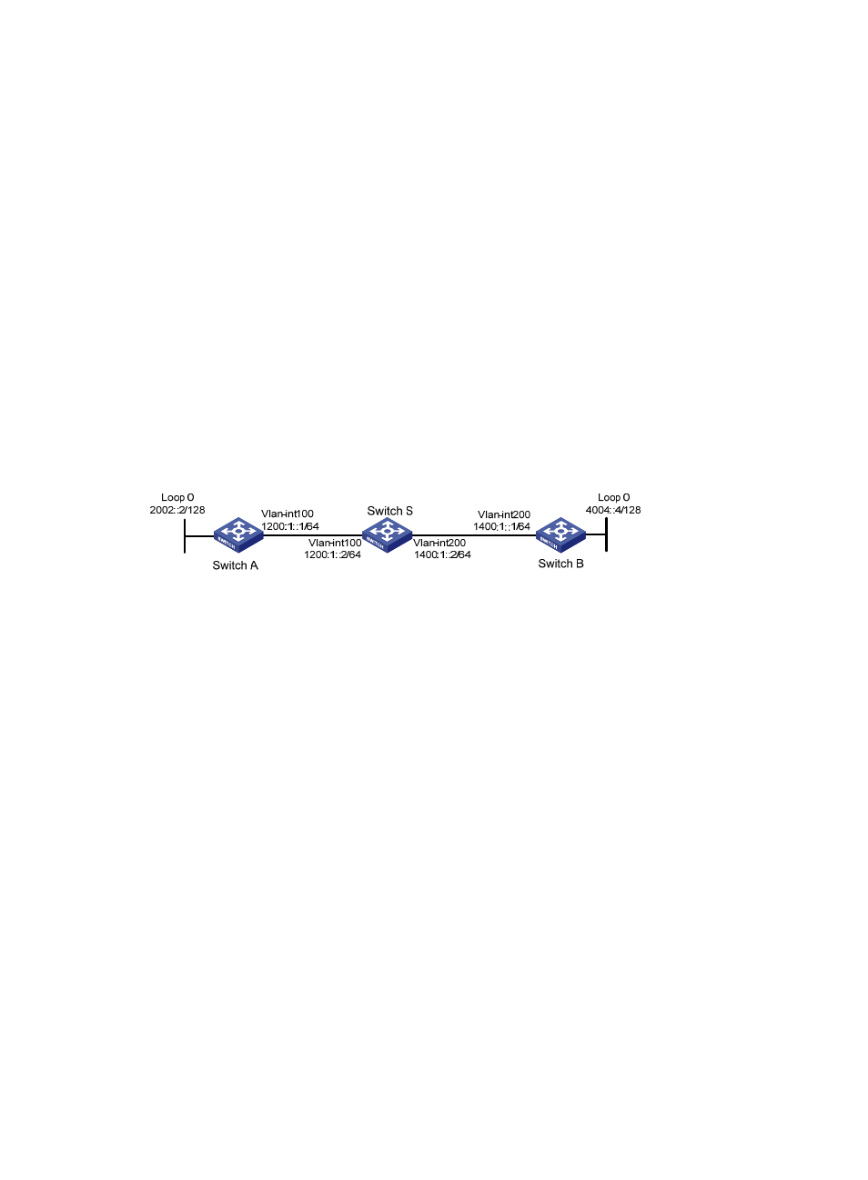
OSPFv3 NSR configuration example
Network requirements
As shown in
, Switch S, Switch A, and Switch B belong to the same AS and OSPFv3 routing
domain. Enable OSPFv3 NSR on Switch S to ensure correct routing when an active/standby switchover
occurs on Switch S.
Figure 94 Network diagram
Configuration procedure
1.
Configure IPv6 addresses for interfaces. (Details not shown.)
2.
Configure OSPFv3:
# On Switch A, enable OSPFv3, and set the router ID to 1.1.1.1.
[SwitchA] ospfv3 1
[SwitchA-ospfv3-1] router-id 1.1.1.1
[SwitchA-ospfv3-1] quit
[SwitchA] interface vlan-interface 100
[SwitchA-Vlan-interface100] ospfv3 1 area 1
[SwitchA-Vlan-interface100] quit
# On Switch B, enable OSPFv3, and set the router ID to 2.2.2.2.
[SwitchB] ospfv3 1
[SwitchB-ospfv3-1] router-id 2.2.2.2
[SwitchB-ospfv3-1] quit
[SwitchB] interface vlan-interface 200
[SwitchB-Vlan-interface200] ospfv3 1 area 1
[SwitchB-Vlan-interface200] quit
# On Switch S, enable OSPFv3, set the router ID to 3.3.3.3, and enable NSR.
[SwitchS] ospfv3 1