Configuration procedure – H3C Technologies H3C S5560 Series Switches User Manual
Page 330
314
•
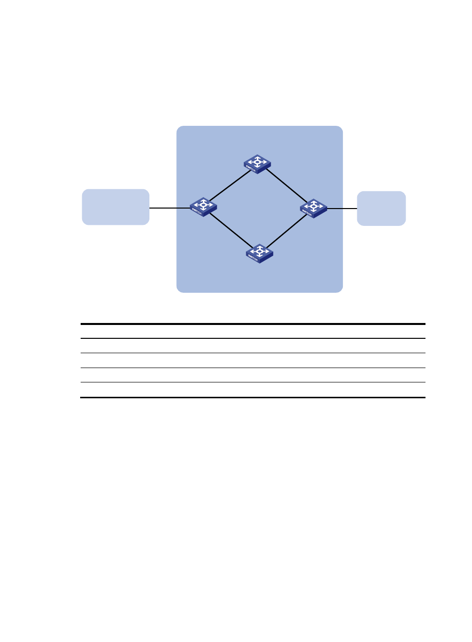
Establish two IBGP connections between Switch A and Switch C. When both paths operate
correctly, Switch C uses the path Switch A<—>Switch B<—>Switch C to exchange packets with
network 1200::0/64.
•
Configure BFD over the path. When the path fails, BFD can quickly detect the failure and notify it
to IPv6 BGP. Then, the path Switch A<—>Switch D<—>Switch C takes effect immediately.
Figure 77 Network diagram
Table 18 Interface and IP address assignment
Device Interface
IP
address
Device
Interface IP
address
Switch A
Vlan-int100
3000::1/64
Switch C
Vlan-int101
3001::3/64
Vlan-int200
2000::1/64
Vlan-int201
2001::3/64
Switch B
Vlan-int100
3000::2/64
Switch D
Vlan-int200
2000::2/64
Vlan-int101
3001::2/64
Vlan-int201
2001::2/64
Configuration procedure
1.
Configure IPv6 addresses for interfaces. (Details not shown.)
2.
Configure OSPFv3 so that Switch A and Switch C can reach each other. (Details not shown.)
3.
Configure IPv6 BGP on Switch A:
# Establish two IBGP connections to Switch C.
[SwitchA] bgp 200
[SwitchA-bgp] router-id 1.1.1.1
[SwitchA-bgp] peer 3001::3 as-number 200
[SwitchA-bgp] peer 2001::3 as-number 200
[SwitchA-bgp] address-family ipv6
[SwitchA-bgp-ipv6] peer 3001::3 enable
[SwitchA-bgp-ipv6] peer 2001::3 enable
[SwitchA-bgp-ipv6] quit
# Create IPv6 ACL 2000 to permit 1200::0/64 to pass.
Switch A
Switch C
AS 200
Switch D
Vlan-int200
Vlan-int201
Switch B
AS 300
Vlan-int101
Vlan-int100
Vlan-int100
Vlan-int101
Vlan-int200
Vlan-int201
AS 100
1200::0/64