Bgp path selection configuration example, Network requirements, Configuration procedure – H3C Technologies H3C S5560 Series Switches User Manual
Page 309
293
Attribute value : MED 0, localpref 100, pref-val 0, pre 255
State : valid, internal-confed, best,
The output shows the following:
•
Switch F can send route information to Switch B and Switch C through the confederation by
establishing only an EBGP connection with Switch A.
•
Switch B and Switch D are in the same confederation, but belong to different sub-ASs. They obtain
external route information from Switch A, and generate identical BGP route entries although they
have no direct connection in between.
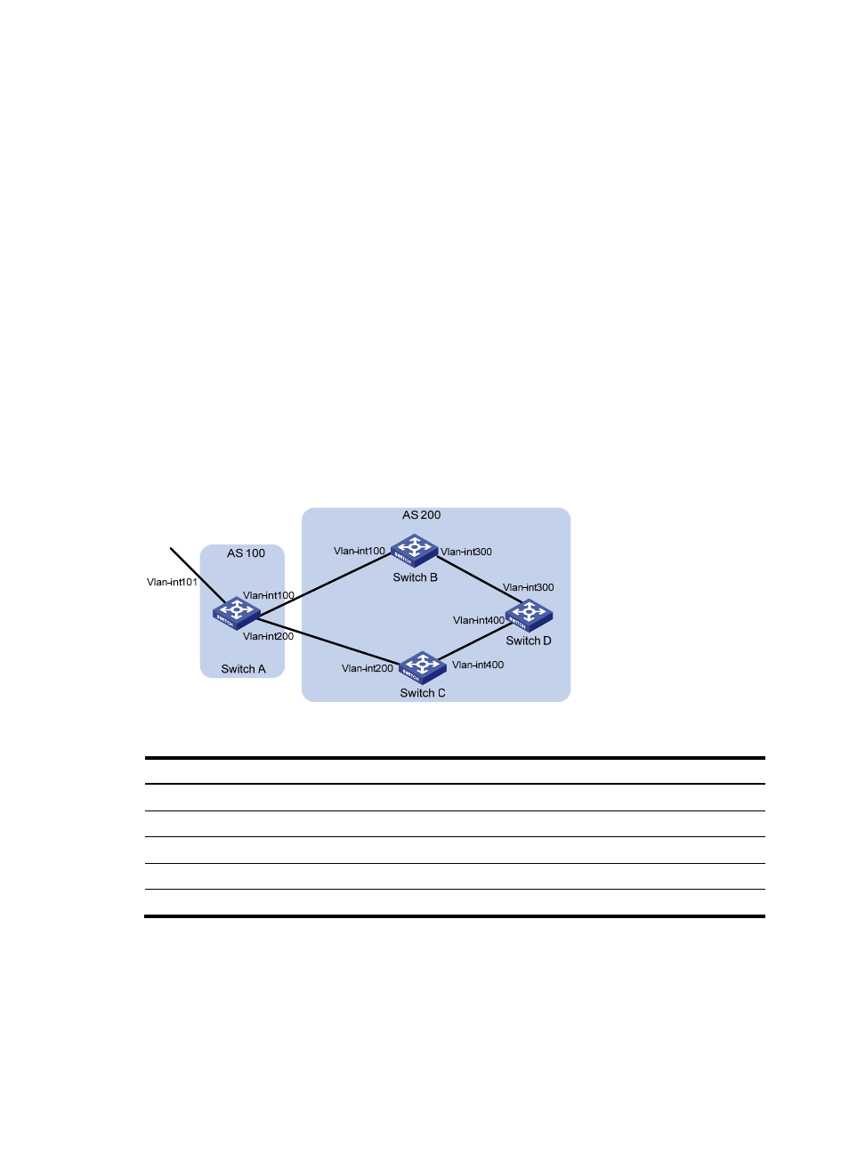
BGP path selection configuration example
Network requirements
As shown in
, all switches run BGP.
•
EBGP runs between Switch A and Switch B, and between Switch A and Switch C.
•
IBGP runs between Switch B and Switch D, and between Switch D and Switch C. OSPF is the IGP
protocol in AS 200.
Configure routing policies, making Switch D use the route 1.0.0.0/8 from Switch C as the optimal.
Figure 70 Network diagram
Table 16 Interface and IP address assignment
Device Interface
IP
address
Device
Interface IP
address
Switch A
Vlan-int101
1.0.0.1/8
Switch D
Vlan-int400
195.1.1.1/24
Vlan-int100
192.1.1.1/24
Vlan-int300
194.1.1.1/24
Vlan-int200
193.1.1.1/24
Switch
C
Vlan-int400
195.1.1.2/24
Switch B
Vlan-int100
192.1.1.2/24
Vlan-int200
193.1.1.2/24
Vlan-int300
194.1.1.2/24
Configuration procedure
1.
Configure IP addresses for interfaces. (Details not shown.)
2.
Configure OSPF on Switch B, Switch C, and Switch D:
# Configure Switch B.