Network requirements, Configuration procedure – H3C Technologies H3C S5560 Series Switches User Manual
Page 70
54
BkLabel: NULL BkNextHop: N/A
Tunnel ID: Invalid Interface: Vlan-interface200
BkTunnel ID: Invalid BkInterface: N/A
The output shows that Switch A communicates with Switch C through VLAN-interface 200.
BFD for RIP configuration example (single hop echo detection
for a specific destination)
Network requirements
As shown in
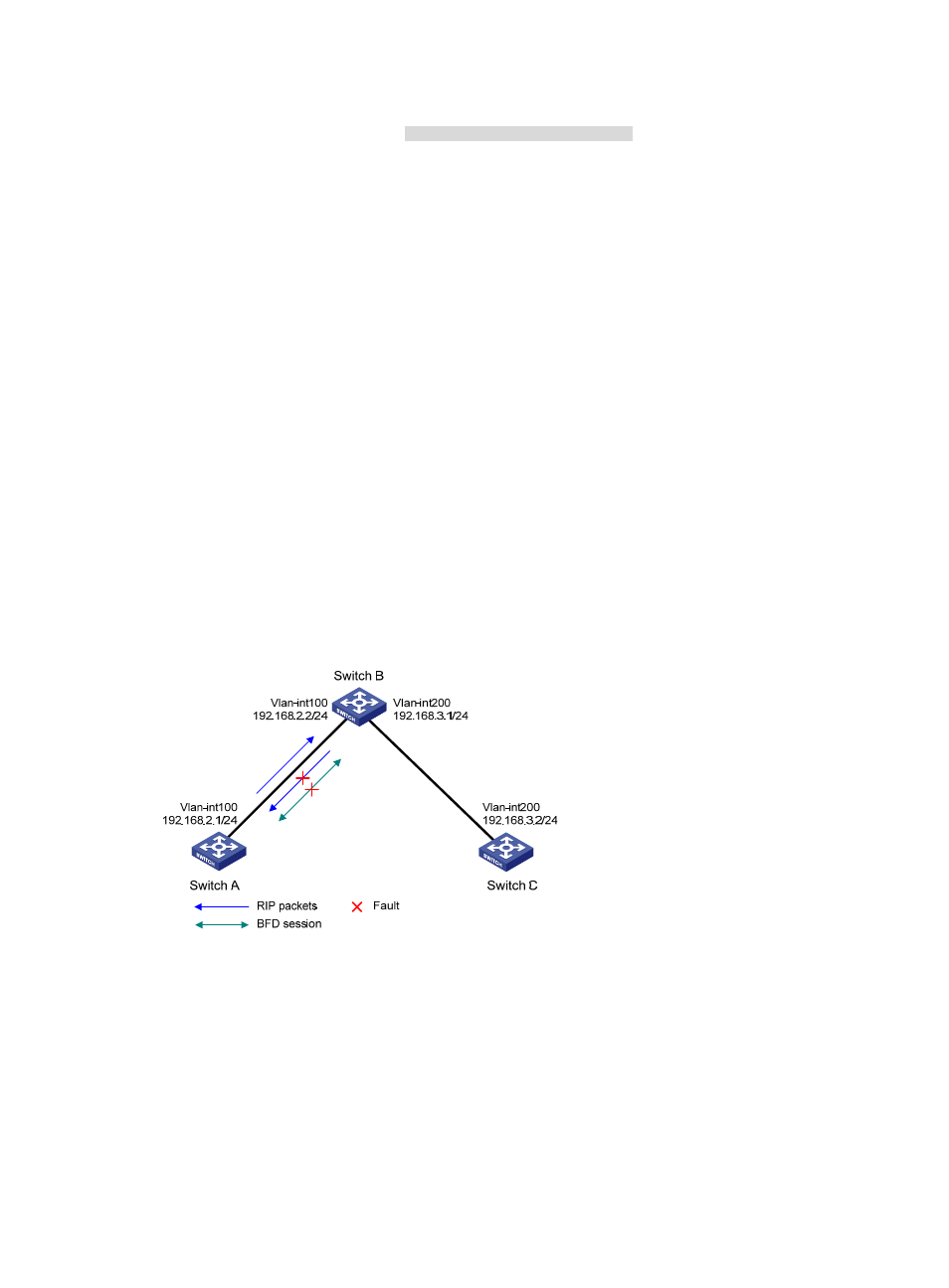
, VLAN-interface 100 of Switch A and Switch B runs RIP process 1. VLAN-interface
200 of Switch B and Switch C runs RIP process 1.
•
Configure a static route destined for 100.1.1.0/24 and enable static route redistribution into RIP on
both Switch A and Switch C. This allows Switch B to learn two routes destined for 100.1.1.0/24
through VLAN-interface 100 and VLAN-interface 200. The route redistributed from Switch A has a
smaller cost than that redistributed from Switch C, so Switch B uses the route through VLAN-interface
200.
•
Enable BFD for RIP on VLAN-interface 100 of Switch A, and specify VLAN-interface 100 of Switch
B as the destination. When a unidirectional link occurs between Switch A and Switch B, BFD can
quickly detect the link failure and notify RIP. Switch B then deletes the neighbor relationship and the
route information learned on VLAN-interface 100. It does not receive or send any packets from
VLAN-interface 100. When the route learned from Switch A ages out, Switch B uses the route
destined for 100.1.1.1 24 through VLAN-interface 200.
Figure 12 Network diagram
Configuration procedure
1.
Configure IP addresses for interfaces. (Details not shown.)
2.
Configure basic RIP and enable BFD on the interfaces:
# Configure Switch A.
[SwitchA] rip 1
[SwitchA-rip-1] network 192.168.2.0
[SwitchA-rip-1] import-route static
[SwitchA-rip-1] quit