Network requirements, Configuration procedure – H3C Technologies H3C S5560 Series Switches User Manual
Page 65
49
The output shows that only one RIP route reaches network 1.1.5.0/24, with the next hop as Switch
B (1.1.1.2) and a cost of 2.
RIP summary route advertisement configuration example
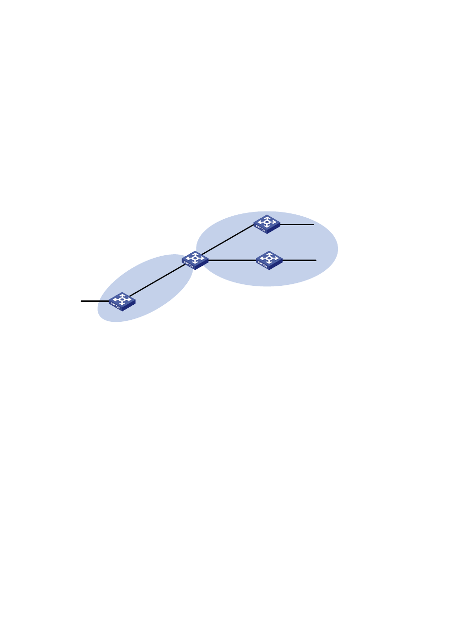
Network requirements
As shown in
, Switch A and Switch B run OSPF, Switch D runs RIP, and Switch C runs OSPF and
RIP.
•
Configure RIP to redistribute OSPF routes on Switch C so Switch D can learn routes destined for
networks 10.1.1.0/24, 10.2.1.0/24, 10.5.1.0/24, and 10.6.1.0/24.
•
To reduce the routing table size of Switch D, configure route summarization on Switch C to advertise
only the summary route 10.0.0.0/8 to Switch D.
Figure 10 Network diagram
Configuration procedure
1.
Configure IP addresses for interfaces. (Details not shown.)
2.
Configure basic OSPF:
# Configure Switch A.
[SwitchA] ospf
[SwitchA-ospf-1] area 0
[SwitchA-ospf-1-area-0.0.0.0] network 10.5.1.0 0.0.0.255
[SwitchA-ospf-1-area-0.0.0.0] network 10.2.1.0 0.0.0.255
[SwitchA-ospf-1-area-0.0.0.0] quit
# Configure Switch B.
[SwitchB] ospf
[SwitchB-ospf-1] area 0
[SwitchB-ospf-1-area-0.0.0.0] network 10.1.1.0 0.0.0.255
[SwitchB-ospf-1-area-0.0.0.0] network 10.6.1.0 0.0.0.255
[SwitchB-ospf-1-area-0.0.0.0] quit
# Configure Switch C.
[SwitchC] ospf
[SwitchC-ospf-1] area 0
Switch A
Vlan-int100
10.2.1.2/24
Switch C
Vlan-int100
10.2.1.1/24
Vlan-int300
11.3.1.2/24
Switch D
RIP
OSPF
Switch B
Vlan-int200
10.1.1.2/24
Vlan-int200
10.1.1.1/24
Vlan-int300
11.3.1.1/24
Vlan-int400
11.4.1.2/24
Vlan-int500
10.6.1.2/24
Vlan-int600
10.5.1.2/24