Ospf nssa area configuration example, Network requirements, Configuration procedure – H3C Technologies H3C S5560 Series Switches User Manual
Page 128
112
[SwitchA-ospf-1-area-0.0.0.1] quit
# Display OSPF routing information on Switch C.
[SwitchC] display ospf routing
OSPF Process 1 with Router ID 10.4.1.1
Routing Tables
Routing for Network
Destination Cost Type NextHop AdvRouter Area
0.0.0.0/0 4 Inter 10.2.1.1 10.2.1.1 0.0.0.1
10.2.1.0/24 3 Transit 10.2.1.2 10.4.1.1 0.0.0.1
10.4.1.0/24 3 Stub 10.4.1.1 10.4.1.1 0.0.0.1
Total Nets: 3
Intra Area: 2 Inter Area: 1 ASE: 0 NSSA: 0
The output shows that inter-area routes are removed, and only one external route (a default route)
exists on Switch C.
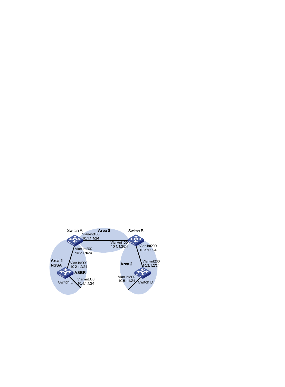
OSPF NSSA area configuration example
Network requirements
As shown in
:
•
Configure OSPF on all switches and split AS into three areas.
•
Configure Switch A and Switch B as ABRs to forward routing information between areas.
•
Configure Area 1 as an NSSA area and configure Switch C as an ASBR to redistribute static routes
into the AS.
Figure 26 Network diagram
Configuration procedure
1.
Configure IP addresses for interfaces.
2.
Basic OSPF configuration example
").
3.
Configure Area 1 as an NSSA area:
# Configure Switch A.