Ospf gr configuration example, Network requirements, Configuration procedure – H3C Technologies H3C S5560 Series Switches User Manual
Page 136
120
# Display the OSPF routing table on Switch B.
[SwitchB] display ospf routing
OSPF Process 1 with Router ID 2.2.2.2
Routing Tables
Routing for Network
Destination Cost Type NextHop AdvRouter Area
10.2.1.0/24 2 Transit 10.2.1.1 3.3.3.3 0.0.0.1
10.3.1.0/24 5 Inter 10.2.1.2 3.3.3.3 0.0.0.0
10.1.1.0/24 2 Transit 10.1.1.2 2.2.2.2 0.0.0.0
Total Nets: 3
Intra Area: 2 Inter Area: 1 ASE: 0 NSSA: 0
The output shows that Switch B has learned the route 10.3.1.0/24 to Area 2.
OSPF GR configuration example
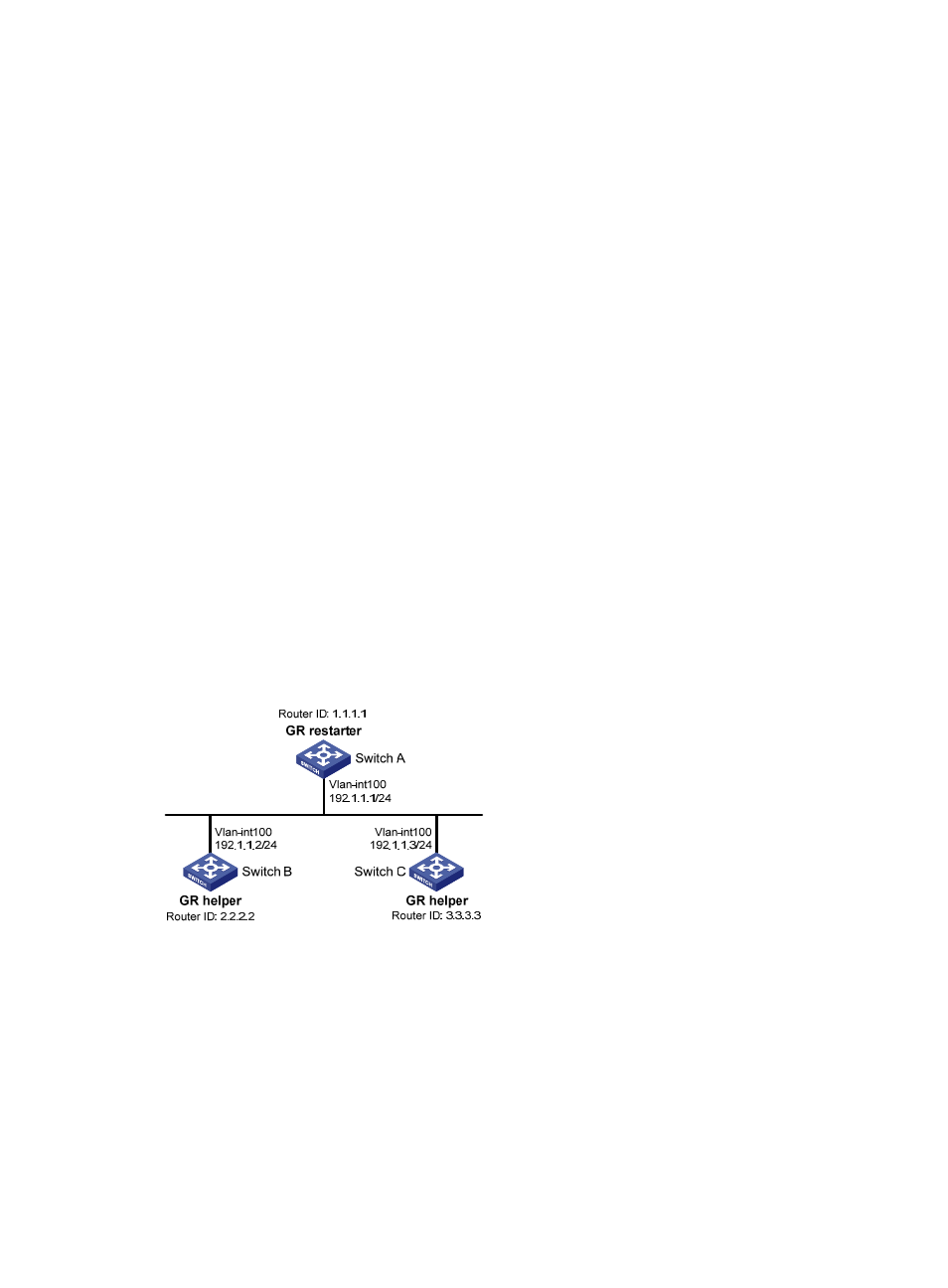
Network requirements
As shown in
:
•
Switch A, Switch B, and Switch C that belong to the same AS and the same OSPF routing domain
are GR capable.
•
Switch A acts as the non-IETF GR restarter. Switch B and Switch C are the GR helpers, and
synchronize their LSDBs with Switch A through OOB communication of GR.
Figure 29 Network diagram
Configuration procedure
1.
Configure IP addresses for interfaces. (Details not shown.)
2.
Enable OSPF:
# Configure Switch A.
SwitchA> system-view
[SwitchA] router id 1.1.1.1
[SwitchA] ospf 100
[SwitchA-ospf-100] area 0
[SwitchA-ospf-100-area-0.0.0.0] network 192.1.1.0 0.0.0.255