Bgp gr configuration example, Network requirements, Configuration procedure – H3C Technologies H3C S5560 Series Switches User Manual
Page 312
296
The output shows that Route 1.0.0.0/8 learned from Switch C is the optimal.
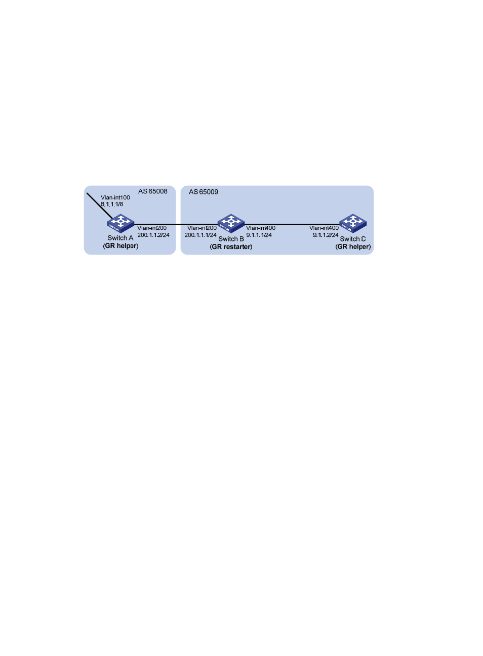
BGP GR configuration example
Network requirements
As shown in
, all switches run BGP. EBGP runs between Switch A and Switch B. IBGP runs
between Switch B and Switch C.
Enable GR capability for BGP so that the communication between Switch A and Switch C is not affected
when an active/standby switchover occurs on Switch B.
Figure 71 Network diagram
Configuration procedure
1.
Configure Switch A:
# Configure IP addresses for interfaces. (Details not shown.)
# Configure the EBGP connection.
[SwitchA] bgp 65008
[SwitchA-bgp] router-id 1.1.1.1
[SwitchA-bgp] peer 200.1.1.1 as-number 65009
# Enable GR capability for BGP.
[SwitchA-bgp] graceful-restart
# Inject network 8.0.0.0/8 to the BGP routing table.
[SwitchA-bgp] address-family ipv4
[SwitchA-bgp-ipv4] network 8.0.0.0
# Enable Switch A to exchange IPv4 unicast routing information with Switch B.
[SwitchA-bgp-ipv4] peer 200.1.1.1 enable
2.
Configure Switch B:
# Configure IP addresses for interfaces. (Details not shown.)
# Configure the EBGP connection.
[SwitchB] bgp 65009
[SwitchB-bgp] router-id 2.2.2.2
[SwitchB-bgp] peer 200.1.1.2 as-number 65008
# Configure the IBGP connection.
[SwitchB-bgp] peer 9.1.1.2 as-number 65009
# Enable GR capability for BGP.
[SwitchB-bgp] graceful-restart
# Inject networks 200.1.1.0/24 and 9.1.1.0/24 to the BGP routing table.