Configuration procedure – H3C Technologies H3C S5560 Series Switches User Manual
Page 141
125
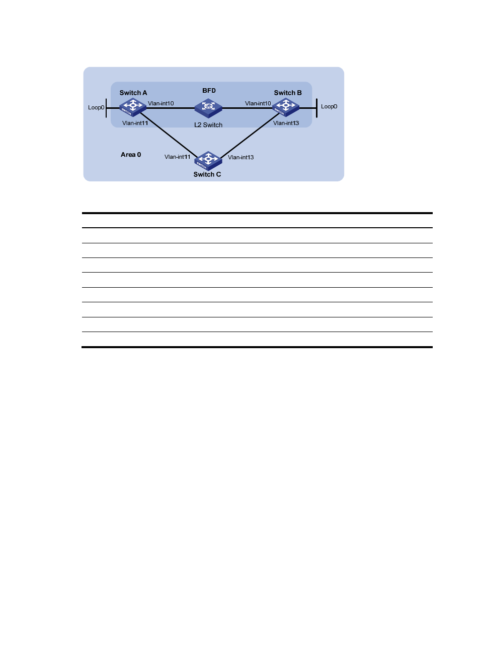
Figure 31 Network diagram
Table 9 Interface and IP address assignment
Device Interface
IP address
Switch A
Vlan-int10
192.168.0.102/24
Switch A
Vlan-int11
10.1.1.102/24
Switch A
Loop0
121.1.1.1/32
Switch B
Vlan-int10
192.168.0.100/24
Switch B
Vlan-int13
13.1.1.1/24
Switch B
Loop0
120.1.1.1/32
Switch C
Vlan-int11
10.1.1.100/24
Switch C
Vlan-int13
13.1.1.2/24
Configuration procedure
1.
Configure IP addresses for interfaces. (Details not shown.)
2.
Enable OSPF:
# Configure Switch A.
[SwitchA] ospf
[SwitchA-ospf-1] area 0
[SwitchA-ospf-1-area-0.0.0.0] network 192.168.0.0 0.0.0.255
[SwitchA-ospf-1-area-0.0.0.0] network 10.1.1.0 0.0.0.255
[SwitchA-ospf-1-area-0.0.0.0] network 121.1.1.1 0.0.0.0
[SwitchA-ospf-1-area-0.0.0.0] quit
[SwitchA-ospf-1] quit
# Configure Switch B.
[SwitchB] ospf
[SwitchB-ospf-1] area 0
[SwitchB-ospf-1-area-0.0.0.0] network 192.168.0.0 0.0.0.255
[SwitchB-ospf-1-area-0.0.0.0] network 13.1.1.0 0.0.0.255
[SwitchB-ospf-1-area-0.0.0.0] network 120.1.1.1 0.0.0.0
[SwitchB-ospf-1-area-0.0.0.0] quit