Watson-Marlow MM440 User Manual
Page 226
3 Functions
Issue 10/06
MICROMASTER 440 Operating Instructions
226
6SE6400-5AW00-0BP0
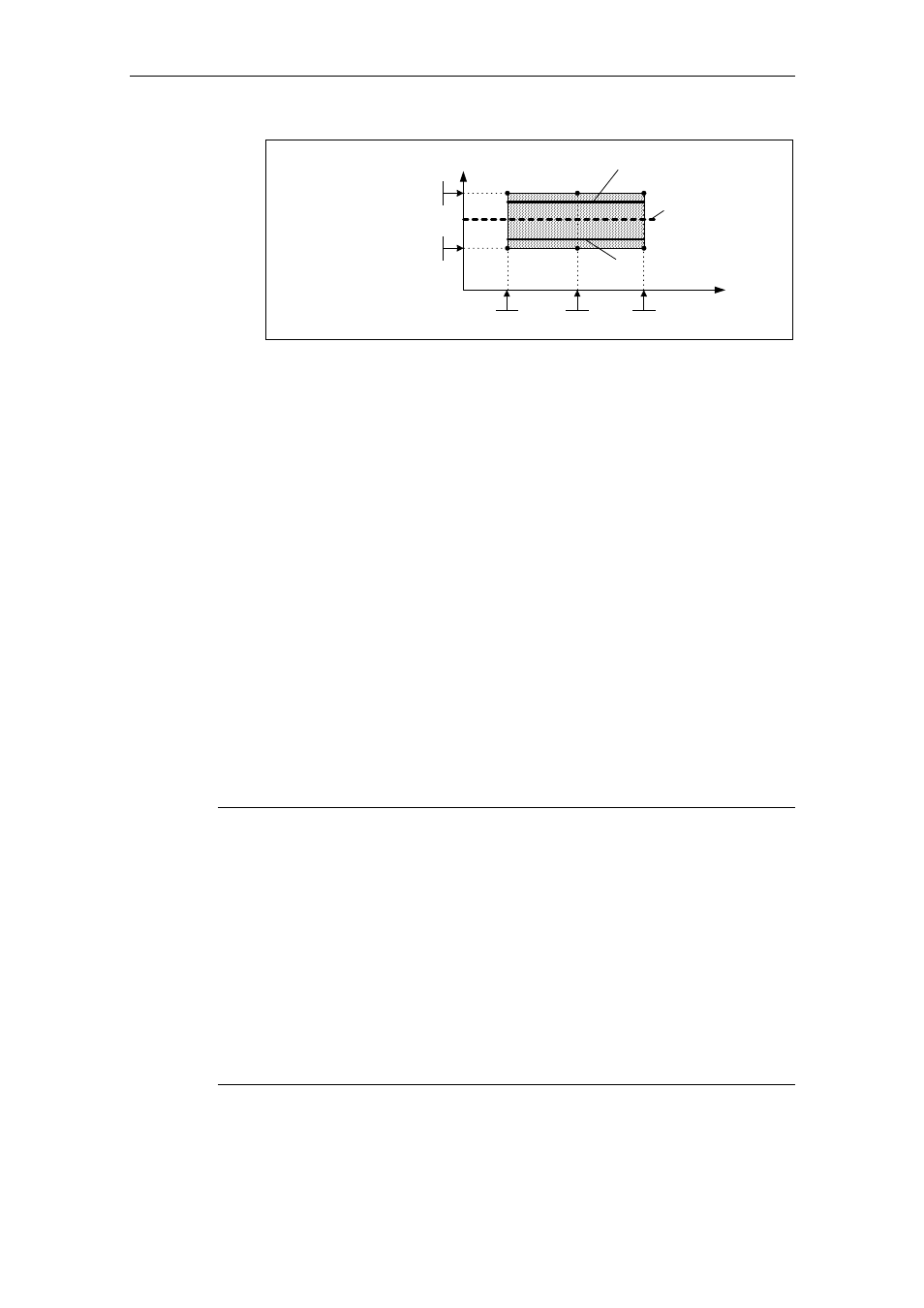
Permissible max.
load characteristic
P2182
|Torque| [Nm]
|Frequency|
[Hz]
P2183
P2185+P2187+P2189
P2184
P2186+P2188+P2190
Permissible min.
load characteristic
Rated load
characteristic
Fig. 3-92
Load torque characteristic with minimum and maximum permissible
load
2. The permissible load torque characteristic must be determined in the operating
range of the plant or system. This characteristic can be determined as follows:
a) Theoretical determination
In this case, the prerequisite is that the load torque characteristic in the
operating range must first be known. Frequently, this is not the case in
practice. Especially changing mechanical effects involve investigations that
require considerable time and costs if they are to be forecast in advance.
b) Practical determination
The load torque characteristic is directly determined at the plant/system
using a "teach-in technique". In this case, the operating range is passed-
through step-by-step and the value pair comprising the actual output
frequency r0021 and actual torque r0031 are read-out in the steady-state
condition. If necessary, this should be carried-out for both directions of
rotation.
3. The position of the tolerance bandwidth (P2182 - P2190) is determined by
defining the 3 points along the characteristic.
4. In order to prevent the torque monitoring responding unnecessarily, dynamic
states should be suppressed using delay time P2192. As a rule of thumb,
P2192 should be > P1120.
Note
¾
The load torque monitoring is active in all 4 quadrants
¾
If it is not possible to determine the min. or max. load torque characteristic at
the drive in operation, then the load torque characteristic should be determined
for operation at rated load. By taking into account the tolerances, the max. or
min. permissible load characteristic can be calculated (e.g. the max. load
characteristic is obtained from the 120% rated load characteristic).
¾
If only a specific frequency range is to be monitored, then it is sufficient to plot
the load characteristic between the frequency thresholds of the envelope curve
(P2182, P2184).
¾
If the drive is only permitted to have one direction of rotation, then the load
characteristic should only be determined for the permissible direction of rotation.
¾
The load characteristic and/or envelope curve determined should be
represented in a frequency-torque diagram, e.g. using Microsoft Excel.